
A gloss meter measures how strongly a surface reflects light in the mirror-like, or specular, direction at a defined angle. It reports a gloss value in Gloss Units (GU), helping manufacturers compare surface finish consistently. The result is useful only when the measurement angle, specimen preparation and test method are known. A number such as 65.2 GU without its angle is an incomplete description.
This guide explains the gloss meter working principle, least count, measurement procedure and industrial applications. It also shows how to separate instrument performance from real product variation, choose an appropriate geometry, calculate useful results and avoid misleading comparisons. The operating workflow is educational: the supplied instrument manual and the agreed test method determine the exact settings, sampling and reporting requirements.
What is a gloss meter and what does it measure?
A gloss meter is an optical surface-testing instrument. Its light source illuminates a small area, and its receiver measures light within a specified angular opening around the specular reflection direction. Electronics convert the response into a calibrated gloss reading. The instrument therefore evaluates one defined aspect of appearance, rather than making a complete judgement about how attractive or durable a product is.
For quality control, this creates a repeatable language for describing finish. A buyer can specify a measurement geometry and an agreed gloss range instead of relying only on words such as shiny, satin or dull. Incoming inspection, process development and final inspection can then compare equivalent measurements. The approved reference and acceptance rule still need to be established by the parties involved.
What are Gloss Units, and can a result exceed 100 GU?
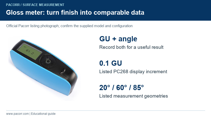
GU is a conventional gloss scale, not percentage reflectance. The scale for the familiar 20°, 60° and 85° geometries is referenced to a defined polished black-glass standard assigned 100 units. A practical calibration tile has its own assigned value for each relevant angle; operators must use those values rather than automatically entering 100.
Surfaces that produce a stronger specular response than the reference can exceed 100 GU, provided the instrument supports that range. This does not mean that a surface reflects more than all the light falling on it. The distinction between a reference-based scale and absolute reflectance is explained in NIST's Specular Gloss measurement publication.
What is the working principle of a gloss meter?
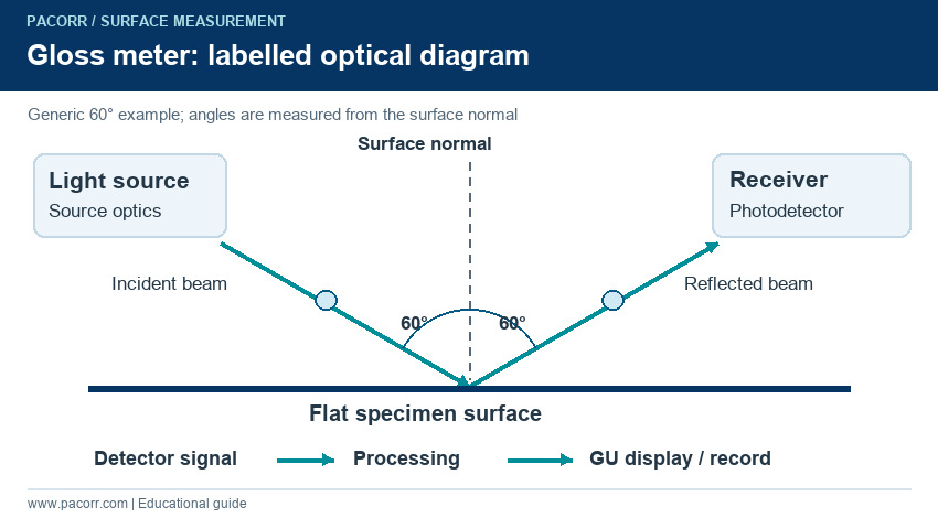
The principle is controlled illumination followed by measurement of specular reflection. Light reaches the specimen at a defined incidence angle, measured from the surface normal: an imaginary line perpendicular to the surface. The receiver views the corresponding reflected direction on the opposite side of that normal. Source and receiver apertures define how much of the reflected beam is collected.
A simplified relationship is: gloss value equals the sample response divided by the reference response, multiplied by the reference's assigned gloss value, under equivalent measurement conditions. This is an explanatory relationship, not a replacement for the instrument's calibration algorithm. NIST describes the importance of matched geometric and spectral conditions in its reference goniophotometer research.
The receiver does not collect all reflected light. Consequently, changing the measurement geometry can change the result even when the specimen has not changed. An instrument must be seated correctly so that its intended optical geometry actually applies to the measured area.
Gloss meter diagram: what does each component do?
The labelled diagram shows a generic optical arrangement, not an undocumented internal drawing of a particular Pacorr model. The source emits light; source optics direct it towards the specimen; the receptor optics collect the selected reflected beam; and a photodetector converts that optical signal into an electrical response. Processing electronics apply the calibration relationship and send the result to the display or data record.
The measuring aperture is the opening placed over the test area. A calibration plate is an external reference used during checking or adjustment; it is not a permanent layer beneath every sample. A stable housing keeps the optical alignment fixed. These distinctions help operators recognise why dirt, rocking, gaps and unsuitable specimen dimensions can affect results even when the display appears normal.
How do you choose 20°, 60° or 85°?
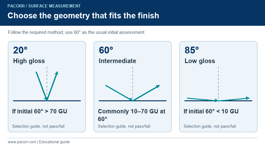
Start with the geometry specified by the customer or applicable method. When developing a suitable routine for conventional finishes, 60° is the usual starting measurement. A widely used screening approach is to move to 20° when the initial 60° reading exceeds 70 GU, and to 85° when it is below 10 GU. Intermediate readings commonly remain at 60°. These are geometry-selection guidelines, not product pass/fail limits. They are described in the NPL Good Practice Guide for the Measurement of Gloss.
| Geometry | Practical role |
|---|---|
| 20° | Better differentiation of high-gloss finishes; selected using the prescribed method or initial 60° assessment. |
| 60° | General-purpose comparison, commonly used for intermediate gloss. |
| 85° | Improved differentiation of low-gloss finishes; needs enough usable specimen area for its footprint. |
Always retain the selected geometry in production records. Changing angles halfway through a trend chart makes apparent process changes difficult to interpret. At a selection boundary, follow the agreed method consistently rather than changing geometry simply to obtain a preferred result.
What is the least count of a gloss meter?
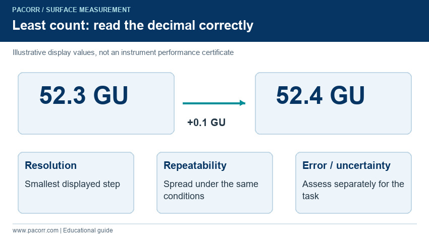
In routine buying discussions, least count usually means the smallest displayed increment, often called division value or display resolution. The Pacorr PC268 Tri Angle Gloss Meter listing specifies 0.1 GU. A display can therefore distinguish successive indications such as 52.3 and 52.4 GU. This specification does not establish that every difference of 0.1 GU between two products is significant.
The JCGM definition of display resolution concerns distinguishable indications. Actual measurement capability also depends on noise, repeat measurements, calibration and specimen positioning. A fluctuating sequence of 52.1, 52.5 and 52.2 GU cannot become stable merely because the screen shows an extra decimal place. Check the complete performance specification and the intended tolerance, rather than buying on least count alone.
How do resolution, accuracy, repeatability and uncertainty differ?
Resolution describes the indication step. Accuracy concerns agreement with the quantity being measured; in purchasing documents, numerical error limits are often used to describe the expected instrument performance. Repeatability concerns agreement under substantially unchanged conditions. Reproducibility addresses results under stated changed conditions. Measurement uncertainty expresses the dispersion attributable to the result using the available information.
| Term | What the laboratory should ask |
|---|---|
| Resolution | What increment is displayed at the relevant range? |
| Error specification | What limit applies, at which angle and range, and under what conditions? |
| Repeatability | How much do repeated measurements of a stable specimen vary? |
| Reproducibility | Which operators, instruments, locations or other conditions were changed? |
| Uncertainty | What contributions were assessed for this measurement and decision? |
The JCGM accuracy definition distinguishes accuracy from precision. A consistent instrument can still show a systematic difference from a reference. Equally, averaging many readings does not automatically remove calibration bias or an incorrect measurement angle.
Which types of gloss meter are available?
Single-angle instruments suit a narrowly defined task when their geometry and range match the specification. Tri-angle instruments provide 20°, 60° and 85° measurements for broader finish evaluation. Specialised instruments may be needed for another geometry, small measurement areas, particular sample shapes or dedicated production-line inspection. These categories should not be treated as interchangeable solely because all report gloss values.
Handheld equipment is useful for accessible finished surfaces. A laboratory fixture can improve positioning when the specimen is difficult to hold consistently. A tri-angle instrument is valuable only if the operator also controls which angle is reported. Confirm whether measurements at several geometries are acquired together or separately on the selected model; do not assume the interface or timing from a generic product description.
Which Pacorr PC268 specifications should buyers check?
The official product page lists the following values. They describe the advertised configuration and should be confirmed against the supplied instrument and quotation.
| Published item | PC268 listing |
|---|---|
| Angles and division value | 20°, 60°, 85°; 0.1 GU. |
| Measuring ranges | 0–1000 GU at 20° and 60°; 0–160 GU at 85°. |
| Measuring areas | 20°: 10 × 10 mm; 60°: 9 × 15 mm; 85°: 5 × 36 mm. |
| Reading time and display | 0.1 second; 3.5-inch TFT. |
| Data interfaces | USB and RS-232; GQC6 software listed. |
| Operating environment | 0–40°C; relative humidity below 85%, without condensation. |
The page's separate error entry does not clearly assign units and conditions to every number. Request a complete specification rather than converting it into an unsupported accuracy claim. Also confirm the exact model, accessories and reference-plate documentation: a photograph or an isolated display example is not a technical specification. Measurement area is particularly important when the product has narrow edges or curved surfaces.
Which standards apply, and what do they actually cover?
Select a standard by material and required measurement procedure, not by choosing the longest list of standard numbers. A supplier listing a standard does not by itself prove that every specimen and every possible configuration complies with its full requirements.
| Standard | Relevant scope and limitation |
|---|---|
| ASTM D523-25 | Specular gloss of nonmetallic specimens using 20°, 60° and 85° geometries. |
| ISO 2813:2014 | Gloss of coatings at those three geometries, for non-textured coatings on flat, opaque substrates; confirmed in 2025. |
| ASTM D2457-21 | Plastic films and solid plastics, including transparent and opaque materials; procedures include geometries beyond 20°/60°/85°. |
| ISO 8254-1:2009 | Paper gloss at 75° using a converging beam; a conventional tri-angle instrument is not an automatic substitute. |
Use the current controlled method required by the purchase contract. Document any departure from its specimen scope. Educational instructions in this article do not replace access to the full procedure or establish a universal number of specimens, conditioning duration or acceptance limit.
How should specimens and the test location be prepared?
Define the product, coating system, surface side and measurement locations before testing. Let the specimen reach the condition required by the method: fresh coating, uncured material and a fully conditioned panel should not be mixed in one comparison. Record any cleaning because removing oil or polishing a surface can change the property being evaluated.
Use an area that supports the instrument without rocking and fully covers the measuring aperture. Avoid labels, joints, obvious handling damage and edges unless the inspection plan deliberately includes them. Handle specimens by their edges where practical. Keep the test location stable and within the instrument's stated environment. When a specimen has been moved from a different temperature, check for condensation and allow the required equilibration before accepting readings.
How do calibration, adjustment and verification differ?
Calibration establishes the relationship between reference values and instrument indications with associated uncertainty. Adjustment changes the instrument response. Verification checks that stated requirements are met. An instrument's menu may call a tile-based adjustment “calibration”, but that menu operation alone is not evidence of a complete external calibration service. The distinction is set out in JCGM's calibration terminology.
Use the correct reference plate, its assigned angle-specific values and the manufacturer's sequence. Inspect the plate without touching its measuring surface. A scratched or contaminated reference can make later readings misleading. Keep records of the reference identity, checks and any adjustment. Where the quality system requires it, use independent verification standards relevant to the working range. Set calibration intervals from use, stability, service history and customer requirements; there is no universal interval for every laboratory.
How do you measure gloss step by step?
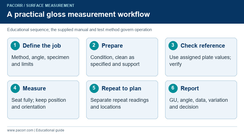
This educational sequence should be turned into a controlled work instruction for the selected model and test method.
- Identify the job: record product, batch, coating or finish, specimen side, method and intended acceptance rule.
- Confirm suitability: check geometry, range, usable surface area and the instrument's operating conditions.
- Prepare the specimen: follow the defined curing, conditioning and cleaning requirements without altering the finish unnecessarily.
- Check the instrument and reference: inspect the aperture, battery and reference plate; perform the required verification or adjustment using its correct assigned values.
- Select the geometry: follow the specification. Where selection is needed, use a documented preliminary assessment and retain the chosen angle in the test record.
- Position consistently: place the aperture fully against the intended area, maintain the planned orientation and prevent rocking or motion.
- Acquire the measurement: allow the instrument to complete its reading, then record the value, angle and location. Flag invalid positioning rather than quietly replacing an inconvenient result.
- Repeat according to the sampling plan: distinguish repeat readings at one position from readings across different positions or specimens.
- Review the session: investigate unusual scatter, inspect check-standard results where required, and retain all valid readings used in the assessment.
- Calculate and report: use the specified summary, rounding and decision rule; identify deviations and the acceptance specification used.
This sequence makes a fast optical reading part of a defensible measurement process. The entire inspection cycle includes preparation, checks and records, not just the instrument's advertised acquisition time.
How many readings are needed, and where should they be taken?
There is no single reading count that is appropriate for every material and purchase specification. Use the method's requirements or an agreed sampling plan. A useful plan identifies the number of specimens, locations per specimen, repeated placements and orientation. For a directional finish, state whether readings follow the process direction, cross it, or are reported separately in both directions.
Repeated measurements without moving the instrument primarily explore short-term reading variation. Lifting and replacing it also includes placement effects. Moving to another region adds spatial variation. Sampling another part adds part-to-part variation. Keeping these levels separate prevents an average from hiding the source of disagreement. Mark a location map outside the measured surface so that a later investigation can reproduce the assessment.
How do you calculate mean gloss, range and gloss change?
The following numbers are illustrative, not a Pacorr performance test or an acceptance specification. Suppose five valid readings at 60° are 52.1, 52.4, 52.3, 52.2 and 52.5 GU. Their sum is 261.5 GU, so the mean is 261.5 ÷ 5 = 52.3 GU. The observed range is 52.5 − 52.1 = 0.4 GU. Report that range as the spread of this dataset, not as the instrument's certified accuracy.
For a comparison with an approved reference mean of 54.0 GU at the same angle, the signed difference is 52.3 − 54.0 = −1.7 GU. The minus sign indicates a lower gloss reading; it does not automatically indicate failure. Maintain equivalent material, geometry and preparation when interpreting that difference.
For a durability example, an initial 80 GU and a later 60 GU at the same geometry give 75% gloss retention: 60 ÷ 80 × 100. Relative gloss loss is 25%, while the absolute change is −20 GU. Retention is a calculated percentage of the initial gloss value; it is not percentage reflectance. Near-zero starting values make percentage changes unstable, so use an agreed reporting approach.
How should pass/fail limits and borderline results be handled?
A product limit belongs to the approved specification, not to the instrument resolution or angle-selection guideline. State whether the limit applies to every location, a specimen mean, a batch mean or a permitted spatial variation. Two inspection teams can disagree even with identical readings if they apply different acceptance rules.
For a hypothetical limit of 50–55 GU at 60°, the example mean of 52.3 GU lies inside the numerical interval. That observation is not a complete conformity decision unless the required sampling, measurement uncertainty and decision rule have also been addressed. Do not round a borderline result in whichever direction makes it pass. Agree the treatment of uncertainty before testing and record the original measurements needed to review the decision.
What should a gloss measurement report contain?
A useful report identifies the specimen and batch, measured surface, instrument and reference identities, method and edition, angle, preparation, orientation, locations and relevant test conditions. Include the individual readings or a traceable data file, the calculation used, the reported result and units, and any departures from the method. If pass/fail is reported, identify the acceptance limits and decision rule.
Keep the reference-check results and adjustment history with the session record. A screenshot showing only a GU value is weak evidence because it may omit the geometry and sample identity. Data export can reduce transcription errors, but an automatically generated file is useful only when its labels and units have been checked. Maintain traceability when transferring readings into spreadsheets or customer reports.
How is gloss different from colour, haze, DOI and roughness?
Gloss measures a defined specular response. Colour measurements describe colour coordinates under a specified measurement system. Reflection haze concerns light scattered close to the specular direction, while distinctness of image, or DOI, concerns the clarity of a reflected image. Surface roughness describes physical topography using a suitable surface-measurement method. These properties can interact without becoming the same measurement.
Consequently, a basic gloss reading does not directly provide colour difference, coating thickness, roughness parameters, adhesion or corrosion resistance. ASTM D523 itself distinguishes other appearance attributes from specular gloss. If two panels have similar GU values but look different, expand the investigation rather than assuming the gloss meter has measured every relevant visual property.
How is gloss used in paints and powder coatings?
Paint laboratories can compare finish between approved samples, development panels and production batches. Record substrate preparation, application method, coating age and relevant processing conditions so that a gloss change can be investigated intelligently. A low reading might prompt checks of the application or finishing process, but the gloss value alone cannot identify the root cause.
For production, measure defined areas and maintain a consistent sequence through the line. Do not substitute gloss for a direct film-thickness or adhesion test. Pacorr's guide to selecting paint-laboratory instruments provides related context for building a test programme that covers several distinct coating properties.
How does automotive surface inspection use gloss data?
Automotive teams may compare approved finishes on coated panels, trim and other suitable components. Different parts need not share the same target: a matte interior finish and a glossy exterior clear coat have different design objectives. The reference, angle and measurement location should therefore be specific to the component.
Curved bodywork and narrow trim can make positioning difficult. Establish a repeatable usable area or appropriate fixture before comparing readings. When appearance differences remain despite similar gloss, assess the other relevant visual attributes separately. See Pacorr's related article on laboratory instruments for automotive surface testing for a broader inspection context.
How is gloss measurement used for plastics and films?
For moulded parts, gloss can help compare finish between approved samples, cavities, production runs and selected positions. Record the moulded surface and orientation because a process direction or textured tool can influence the measured appearance. Do not mix measurements from a flat plaque and an inaccessible curved product without demonstrating that the comparison is meaningful.
For films, establish the measured side, support and backing. ASTM D2457 includes procedures for different geometries; the appropriate procedure must be selected rather than assuming that every plastic requires 60°. Comparisons between transparent and opaque films are specifically problematic. Keep specimen type and measurement procedure consistent when using gloss to monitor production changes.
Can the same meter test printed packaging and paper?
Gloss data can support comparisons of varnished, laminated or printed packaging when the agreed method fits the surface. Measure defined regions rather than mixing printed solids, unprinted areas, folds and seams. Record the side, finishing process and conditioning used for the comparison. A gloss change can guide investigation, but it is not a direct measurement of ink or varnish thickness.
Paper-specific methods may use a different optical arrangement. ISO 8254-1 specifies 75° with a converging beam, so a 20°/60°/85° instrument should not be presented as universally suitable for that requirement. Confirm the requested paper or print standard before purchasing. A measurement at a different angle can be useful internally while still being unsuitable for a contractual compliance report.
What about furniture, laminates, ceramics and metal finishes?
Furniture coatings, decorative laminates and suitable ceramic finishes may be compared against approved references when their geometry and specimen conditions are controlled. Define how grain, texture, joints and decorative features are sampled. A numerical finish target is most useful when accompanied by a practical location and orientation instruction.
Bare or highly polished metals require particular care because their optical response and appropriate methods can differ from nonmetallic coatings. Do not assume ASTM D523 covers every metal surface, or equate a high GU value with corrosion protection. Ask for a demonstration on representative specimens and an agreed interpretation. Matching the application is more useful than selecting a meter only by its maximum reading.
How do curvature and small specimen size affect results?
The instrument expects a particular surface position beneath its optics. A curved specimen can change the local normal across the measurement footprint, while an undersized specimen may not cover the aperture. Rocking, gaps or an edge within the measured area can therefore invalidate a comparison. The length of the footprint matters as well as its nominal area.
Use a suitably designed fixture, smaller-aperture instrument or another validated arrangement when required. Do not force a standard handheld meter against a shape it cannot measure consistently. If a flat witness panel is used to monitor a coating process, identify it as a witness panel; it is not automatically the measured gloss of every curved production component.
How should transparent and textured surfaces be assessed?
With transparent specimens, the backing and rear-surface contributions can affect the optical response. Define the support, backing, thickness and measured side, and follow the selected procedure. Do not compare a loose film over a dark bench with the same film over a light card and attribute the entire difference to manufacturing.
For textured or directional surfaces, choose representative positions and maintain the agreed orientation. A flat measurement foot does not make the surface optically uniform. ISO 2813's principal scope is non-textured coatings on flat opaque substrates; results outside that scope need a justified comparative procedure. Record the limitation and avoid claiming that a single average captures the complete visual appearance of an embossed or strongly textured product.
What causes unstable or unexpectedly different readings?
Investigate the measurement system before changing the production process. Begin with the reference plate and positioning, then compare repeated readings at one location with readings across the surface. This helps distinguish a measurement problem from a real variation pattern.
| Symptom | Checks before accepting the result |
|---|---|
| Readings change after every placement | Rocking, curvature, location, orientation, aperture coverage and contamination. |
| All samples shift after adjustment | Correct tile identity and values, tile cleanliness, selected angle and adjustment record. |
| Two operators disagree | Placement instruction, sample side, angle, cleaning, location map and transcription. |
| One region differs consistently | Repeat the location check, then investigate actual local finish or process variation. |
| Display reaches its limit | Verify range and geometry; do not report an over-range indication as an exact value. |
Keep valid unusual readings visible in the record. Excluding a result requires a documented reason such as a known placement failure, rather than dissatisfaction with the number.
How should the meter and calibration plate be maintained?
Protect the optical opening from dust, impact and deposits. Store the reference plate in its protective case and avoid touching its active surface. Follow the manufacturer's approved cleaning method for the specific plate and optics; an aggressive solvent or polishing compound can damage the reference and change its value. Do not open the optical assembly for routine cleaning unless the service instructions explicitly permit it.
Recheck performance after a drop, repair, suspected contamination or a persistent unexplained shift. Record battery and charging issues that affect operation. Maintain a history of verification readings to identify drift, and retain calibration documentation. A routine tile check is useful, but it should be part of a defined measurement-control system rather than a substitute for all servicing or calibration requirements.
How do you select the right gloss meter for your laboratory?
Begin with the material, surface shape, required standard, geometry, expected gloss range and acceptable variation. Then check whether the aperture fits the actual product and whether the performance specification is suitable for the tolerance. Ask to test representative samples, including difficult matte, curved, narrow or textured examples, rather than relying only on an ideal demonstration tile.
Next assess the reference plate, calibration support, data export, software compatibility, portability and service arrangements. Confirm what the quotation includes. A good selection decision connects each feature to a real task: additional geometries support different finishes, data handling supports traceability, and a suitable aperture supports valid positioning. Extra decimal places alone do not establish better product decisions.
What affects gloss meter price and quotation?
A current fixed selling price was not verified on the official product page, so a quotation is required. Cost depends on the geometry set, measurement range and aperture, performance specification, reference standards, calibration documentation, software, accessories and service scope. Freight, taxes and any installation or training arrangements should be clarified in the offer.
Send the supplier your specimen dimensions, finish types, required methods and the tolerance you need to assess. Request the exact model and an itemised scope so that quotations can be compared fairly. A lower initial price is not necessarily the lower operating cost if extra fixtures, unsupported data formats or unsuitable geometry make routine inspection difficult.
Frequently asked questions about gloss meters
Is 0.1 GU least count the same as ±0.1 GU accuracy?
No. A 0.1 GU display increment describes resolution. Accuracy-related error limits, repeatability, calibration and measurement uncertainty must be assessed separately for the relevant angle and range.
Should I always use the 60° measurement angle?
No. Follow the specified method. The 60° geometry is a common starting point, while 20° is useful for high gloss and 85° for low gloss; some material methods require other geometries.
Can gloss units be written as percentage reflectance?
No. GU is a reference-based gloss scale. A result of 80 GU does not mean that the specimen reflects 80% of incident light.
Why can a gloss reading exceed 100 GU?
A specimen can produce a stronger specular response than the reference used to define the scale. Values above 100 GU are possible within a suitable instrument's measurement range.
Does a gloss meter measure colour or coating thickness?
A basic gloss measurement does not directly measure either property. Use an appropriate colour-measurement instrument or coating-thickness method when those quantities are required.
Can I compare readings taken at different angles?
Do not treat them as interchangeable results or combine them into one average. Compare measurements at the same specified geometry and retain separate records for different angles.
Must every calibration plate be set to 100 GU?
No. Use the plate's assigned values for the applicable angles and the instrument manufacturer's procedure. A practical reference plate is not automatically exactly 100 GU at every angle.
How many gloss readings should I take?
Use the applicable test method or an agreed sampling plan. Define specimens, positions, repeated placements and orientation; no universal reading count suits every product.
Can a tri-angle meter perform every paper gloss test?
No. Some paper methods require 75° and a particular beam geometry. Confirm the required standard before substituting a 20°/60°/85° instrument.
What information should I provide when requesting a quotation?
Provide the material, finish, specimen dimensions and shape, required standard and angles, expected gloss range, tolerance, data needs and calibration-documentation requirements.
Discuss your gloss-testing application with Pacorr
For selection guidance, share representative specimens or a clear description of the product, surface dimensions, finish range and customer specification. Pacorr can then discuss the listed Gloss Meter configuration, quotation and the information needed to assess suitability.
Contact Pacorr Testing Instruments at +91-8882149230 or info@pacorr.com. Request confirmation of the supplied model, applicable measurement geometries, reference-plate values, calibration support and any specimen-specific limitations before placing an order.