
Last updated: 21 October 2026
Verified by: Kishore Gupta - Editorial checks
Small dimensional variations can affect how a component fits, aligns, or performs in an assembly. For manufacturers working with fine edges, miniature parts, and closely spaced features, reliable measurement is essential for maintaining product quality.
Vision Measuring Systems help manufacturers inspect component dimensions using optical imaging and measurement software. However, a clear, magnified image alone does not establish measurement accuracy. The system’s performance must also be evaluated against defined requirements.
ISO 10360-7 provides a framework for performance testing of a specific category of coordinate measuring machines equipped with imaging probes. Understanding its scope helps manufacturers ask better questions when selecting equipment and planning verification.
This guide explains how Vision Measuring Systems work, where ISO 10360-7 applies, and which practical checks support dependable inspection.
What Are Vision Measuring Systems?
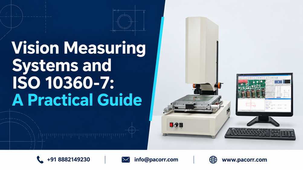
Vision Measuring Systems are dimensional inspection instruments that combine cameras, optics, controlled illumination, measuring stages, and software. They capture images of component features and use coordinate information to calculate dimensions. Depending on the equipment and software configuration, measurements can include distances, diameters, angles, and relationships between visible features. Optical measurement does not require a contact probe to touch the feature being inspected. This makes it useful for applications involving small or delicate components where physical contact may be difficult or undesirable. Typical applications include electronic components, precision machined parts, and moulded plastic components. The suitability of a system depends on the actual part geometry, surface characteristics, and measurement requirements.
How Does a Vision Measuring System Work?
A vision measuring system identifies features within an image and relates their positions to a calibrated measurement system.
The main stages are:
- Positioning: The operator places and secures the component on the measuring stage.
- Illumination: Suitable lighting makes the required edges or surface features visible.
- Imaging: The camera and optics capture a magnified view.
- Feature detection: The operator or software identifies the points and boundaries to measure.
- Calculation: The software calculates dimensions from the selected features and coordinate data.
- Reporting: Results are recorded for comparison with drawing requirements.
The quality of the result depends on the complete process. Part positioning, lighting, focus, alignment, and feature selection all deserve attention.
What Is ISO 10360-7?
ISO 10360-7:2011 forms part of the ISO 10360 series for coordinate measuring machines, commonly called CMMs. It specifies acceptance and reverification tests for CMMs equipped with imaging probing systems. Its scope covers Cartesian CMMs using imaging probes in discrete-point probing mode. In simple terms, these systems use image information to identify individual measurement points. Acceptance testing evaluates performance against stated requirements. Reverification allows users to check that performance periodically during service.
ISO 10360-7 does not automatically apply to every camera-based inspection device or optical measuring instrument. Buyers should confirm the machine architecture and probing method before including the standard in a purchase specification.
Why Is ISO 10360-7 Relevant When Buying a Vision Measuring System?
An accuracy claim is more useful when the supplier explains the method and conditions used to establish it. For buyers, a defined performance-testing framework provides a basis for discussing what the machine must demonstrate before acceptance. It also helps quality teams plan how performance will be reviewed during use.
When evaluating a supplier’s proposal, ask:
- Which measurement characteristics does the stated specification cover?
- Under what operating and environmental conditions does it apply?
- Which test method supports the performance claim?
- Is supporting documentation available for the proposed configuration?
- What arrangements are available for subsequent verification?
These questions help purchasing and quality teams agree on measurable requirements before ordering equipment.
Resolution, Repeatability, and Accuracy: Understanding the Difference
Resolution, repeatability, and accuracy describe different aspects of measurement performance. They should not be treated as interchangeable terms.
| Term | Practical meaning |
| Resolution | The smallest change the system can indicate or distinguish. |
| Repeatability | How closely repeated measurements agree under the same conditions. |
| Accuracy | How close a measurement is to the reference value. |
| Measurement uncertainty | The quantified doubt associated with a measurement result. |
A system can produce closely grouped readings while still having a systematic error. Similarly, displaying additional decimal places does not prove that every displayed digit is accurate. When selecting Vision Measuring Systems, focus on demonstrated capability for the dimensions and tolerances on your component drawings.
Practical Inspection Procedure for Vision Measuring Systems
The following workflow provides guidance for routine component inspection. Formal acceptance or reverification testing requires the complete applicable standard and an approved procedure.
Step 1: Review the Component Drawing
Identify the dimensions, tolerances, datums, and features that require inspection.
For example, measuring a hole diameter and checking its position are different tasks. The inspection method must address the requirement specified on the drawing.
Prepare a measurement plan before setting up the instrument.
Step 2: Confirm the System’s Capability
Check that the component and fixture fit within the available measuring range. Confirm that the camera can view the required features clearly.
For equipment evaluation, request a demonstration using representative components. Include difficult features such as reflective surfaces, shallow edges, or recessed areas.
A successful measurement on a demonstration sample does not establish suitability for every production part.
Step 3: Prepare and Secure the Component
Remove contamination that could interfere with inspection. Position the component securely without applying forces that could distort it.
Use a consistent fixture arrangement and document how the part should be loaded. Repeatable positioning helps operators reproduce the approved inspection setup.
Step 4: Adjust Lighting, Focus, and Magnification
Lighting influences how the imaging system detects an edge. Transmitted illumination can reveal a component’s silhouette, while reflected illumination helps reveal surface features.
Select settings that make the intended measurement boundary clear. Record or save these settings for future inspections.
The objective is to obtain a suitable image for measurement, rather than simply the brightest or most visually appealing image.
Step 5: Establish the Measurement Alignment
Create the coordinate system using the required reference features.
Check that the alignment reflects the drawing’s measurement intent. For repeated batches, use the same approved alignment method and inspection sequence.
Step 6: Check Repeated Measurements
As an initial application check, measure a representative feature several times. Then remove and reposition the component and repeat the measurements.
Review whether the results change with loading, alignment, or operator technique.
This preliminary check can identify setup problems, but it does not replace formal machine verification or a planned measurement system study.
Step 7: Record and Evaluate the Results
Record the component identification, drawing revision, operator, inspection settings, and measurement results.
Compare the results with the specified tolerances. Where a result is close to a tolerance limit, consider measurement uncertainty and apply the organisation’s agreed decision rule before accepting or rejecting the component.
What Should You Request in a Verification Report?
Before purchasing equipment, agree on the evidence needed to support its performance claims.
A practical report-review checklist includes:
- Machine model and serial number.
- Standard and edition used.
- Tested configuration and relevant operating settings.
- Reference artefacts and their calibration information.
- Environmental conditions during testing.
- Measured results and applicable performance limits.
- Measurement uncertainty and the conformity decision, where relevant.
- Test date and identification of the testing organisation.
Ask the supplier to explain what the report covers. A general product brochure should not be treated as evidence that a particular installed machine has passed an acceptance test.
How to Choose Vision Measuring Systems for Your Application
Begin with the inspection requirement, then assess the equipment against it.
| Selection factor | What to evaluate |
| Component size | Measuring range, stage capacity, and fixture space. |
| Feature visibility | Suitability of optics and illumination for the actual surfaces and edges. |
| Drawing tolerances | Demonstrated measurement capability for the required dimensions. |
| Inspection volume | Operator involvement and practical inspection cycle time. |
| Software and reporting | Required measurement functions and usable inspection records. |
| Technical support | Training, maintenance, and performance-verification arrangements. |
Consider the full range of components you intend to inspect. A system that measures a flat outline successfully may need a different setup or sensor to inspect another type of feature.
Sharing drawings and sample parts with the supplier helps establish suitability before purchase.
Vision Measuring Systems from Pacorr
Pacorr offers a Vision Measuring System for dimensional inspection using optical imaging and measurement software. Its published PC-SVI-IMG-3D model information lists manual operation and a measuring range of 150 × 100 × 100 mm. www.pacorr.com
To evaluate the system for your application, share your component drawings, sample parts, tolerances, and expected inspection volume with Pacorr.
If ISO 10360-7 testing is part of your purchase requirement, request confirmation of its applicability and supporting documentation for the proposed configuration.
Contact Pacorr to discuss your component inspection requirements and request a quotation for a Vision Measuring System.
Frequently Asked Questions
Can a vision measuring system inspect every feature on a component?
No. Measurement capability depends on feature visibility, geometry, surface condition, optics, software, and available sensors. Confirm the inspection method for each critical feature.
Does higher magnification guarantee greater measurement accuracy?
No. Magnification helps reveal detail, but accuracy depends on the complete measuring system and inspection process. Equipment condition, alignment, lighting, and measurement technique also matter.
Does ISO 10360-7 certify the components inspected by the machine?
No. The standard concerns machine performance testing. It does not certify every component subsequently inspected on that machine.
How often should a vision measuring system be checked?
Establish a checking schedule based on usage, performance history, manufacturer guidance, and quality requirements. Also assess whether relocation, repair, or system changes require additional checks before routine inspection resumes.
What information should I provide when requesting a quotation?
Provide component dimensions, drawings, tolerances, sample parts where possible, expected inspection volume, and reporting requirements. Include any required acceptance-testing or verification documentation so the supplier can address it in the proposal.
Recent Blogs
Enhance your understanding of testing and precise quality control indistinct applications with our
knowledge based articles coming from top editors of industry leaders.

Our USP's
Demonstration of Machine
- Try Before You Decide
- Experience Before You Invest
- See It in Action – Free Demo
Global Reach
- Delivering Excellence Worldwide
- Serving Across Borders
- Your Global Supply Partner
On-Site Support
- Support That Comes to You
- On-Ground Assistance, Anywhere
- We Reach Where You Are
Team Strength
- Powered by Expert Minds
- Driven by Skilled Professionals
- Engineering Excellence Team
Manufacturing
- Precision-Driven Manufacturing
- Smart & Automated Production
- Engineered In-House Excellence
