A compression test machine applies a controlled squeezing force to a specimen and measures the load it resists. Depending on the equipment and test method, it can also measure deformation and support calculations of compressive strength, stiffness or other properties. CTM stands for Compression Testing Machine.
The right machine depends on what you are testing. A concrete cylinder, a plastic specimen and a corrugated carton require different loading arrangements and result interpretations. Selecting equipment starts with the specimen, the applicable test method and the decision the result must support.
What is the full form of CTM?
The full form of CTM is Compression Testing Machine. “Compression test machine” and “compression testing machine” are common names for equipment that evaluates behaviour under a compressive load.
In a civil-engineering laboratory, CTM often refers to a dedicated concrete-strength testing machine. In manufacturing, compression testing may use a universal testing machine fitted with compression platens or an application-specific tester. The abbreviation alone does not establish the machine's capacity, measuring capabilities or suitability for a particular material.
Compression testing machine working principle
A specimen is positioned between two loading surfaces called platens. The machine moves one platen towards the other, bringing the surfaces into contact and applying the loading sequence required by the test method.
The drive produces movement; the force-measuring system records the resulting load. A controller may regulate movement or another supported control variable. Depending on the system, displacement is obtained from crosshead travel or a separate sensor. The test stops at a defined condition, such as a target deformation, specified force or detected failure.
Four terms help explain the results:
| Quantity | Meaning | Typical units |
|---|---|---|
| Force | The total compressive load applied to the specimen | N or kN |
| Stress | Force divided by an appropriate loaded area | MPa or N/mm² |
| Strain | Change in a defined specimen length divided by its original length | Ratio or % |
| Hydraulic pressure | Pressure in the machine's hydraulic circuit | bar or MPa |
Hydraulic pressure and specimen stress are different quantities. A pressure-based force measurement requires the machine's calibrated conversion; the pressure-gauge value is not automatically the material's compressive strength.
Compression testing machine diagram and components
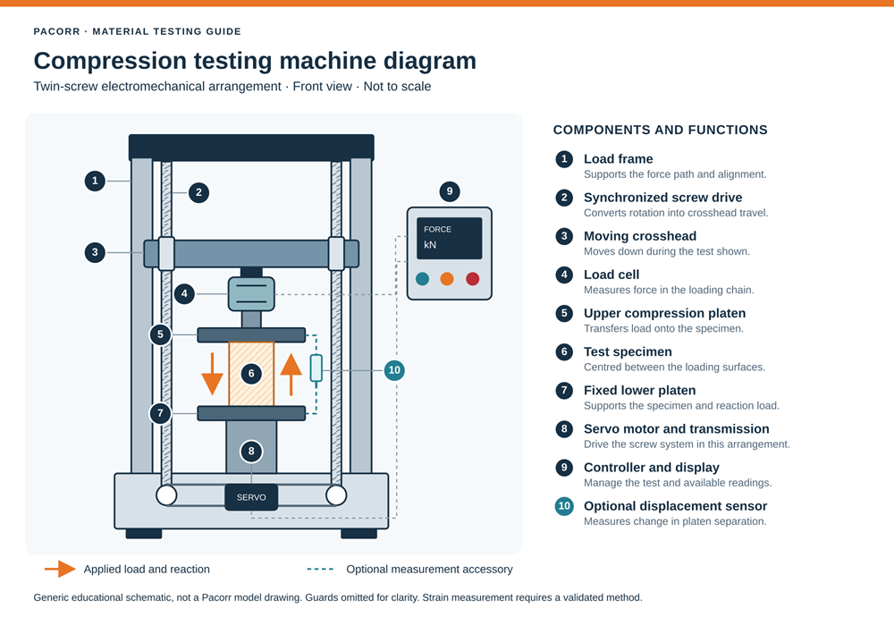
The compression testing machine diagram below shows a twin-screw electromechanical arrangement. A servo motor drives synchronized screws, which move the crosshead. Force passes through the load cell and upper platen into the specimen, while the lower platen and frame support the reaction.
Figure 1. Generic electromechanical compression testing arrangement. The optional sensor measures platen separation. The illustration is not a Pacorr model drawing; guards are omitted for clarity.
The numbered components have distinct roles:
- 1–3: Frame, screws and crosshead support and guide the loading assembly.
- 4: Load cell measures force in the load path.
- 5–7: Upper platen, specimen and lower platen form the compression interface.
- 8–9: Motor, transmission and controller provide movement and execute the available test settings.
- 10: Optional displacement sensor records the change in platen separation. Its suitability for a particular strain measurement must be established by the test method.
A hydraulic compression testing machine uses a hydraulic actuator instead of the illustrated screw drive. Sensor positions, moving parts and platen arrangements vary between designs. An educational diagram should therefore identify the machine type it represents.
Types of compression testing machines
Machines can be classified by how they generate movement and how they control and report a test. These are separate choices.
| Drive type | Operating principle | Selection considerations |
|---|---|---|
| Hydraulic | Pressurized fluid moves an actuator | Required force, control performance, hydraulic maintenance and installation |
| Electromechanical | A motor and mechanical transmission move the crosshead | Force range, travel, speed control, fixtures and measurement requirements |
Both technologies are used in material testing. Capacity and performance depend on the complete machine design; neither drive type is automatically more accurate in every application.
Manual operation, digital indication, automatic control, touch-screen operation and computer reporting describe other features. A hydraulic machine can be automatic, and an electromechanical machine can use a touch screen. A digital readout alone does not establish data export or closed-loop force control.
CTM versus UTM versus box compression tester
| Equipment | Typical purpose | Selection priority |
|---|---|---|
| Dedicated concrete CTM | Compression testing of suitable concrete specimens | Force capacity, specimen accommodation, platens and method-specific control |
| UTM with compression fixtures | Compression and other supported mechanical tests | Available fixtures, measurement range, control modes and strain accessories |
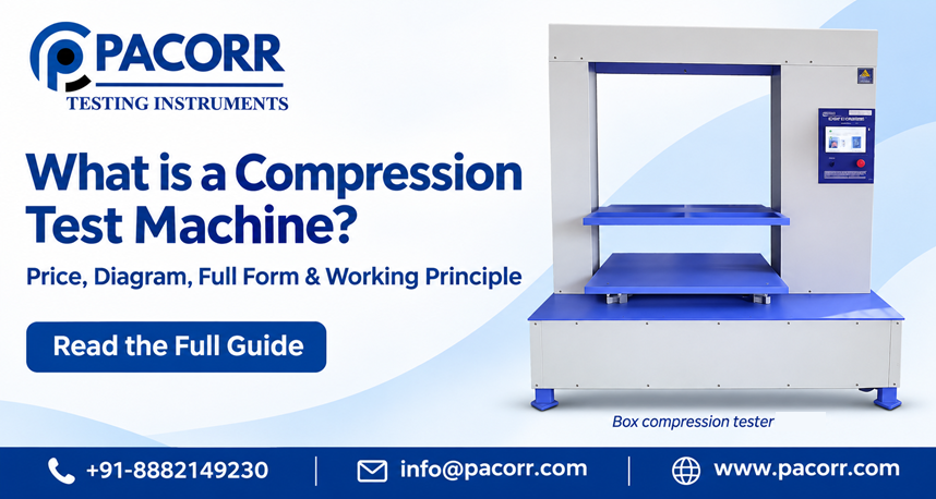
| Box compression tester | Compression resistance of cartons or packages | Platen size, usable height, expected force and package-test requirements |
A UTM's versatility depends on its installed configuration. For broader terminology, see Pacorr's guide to UTM full form and working principle. Equipment names do not make these three systems interchangeable.
Where is compression testing used?
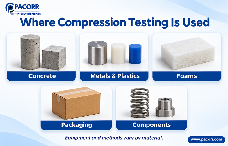
Concrete and construction materials: Laboratories assess compressive strength using specified specimen preparation, curing and loading procedures. Concrete results depend on factors including specimen geometry, age and curing history; comparisons require comparable test conditions.
Metals and rigid plastics: Suitable tests can characterize yielding, deformation and stiffness. A specimen may flatten or barrel rather than break sharply, so a maximum-force reading alone may not define a meaningful compressive strength. The selected method determines the reported property.
Foams: Compression measurements help characterize cushioning and resistance at defined deformation levels. Flexible foam and rigid foam require different methods. Pacorr's introduction to foam compression testing provides additional application context.
Packaging: Testing evaluates how an assembled carton or package responds to compression. Empty and filled packages can behave differently because contents and internal supports may carry load. See box compression testing for corrugated packaging for this application.
Components: Springs, containers and other parts may require application-specific fixtures and a force–movement result rather than a bulk material-strength value.
How is a compression test performed?
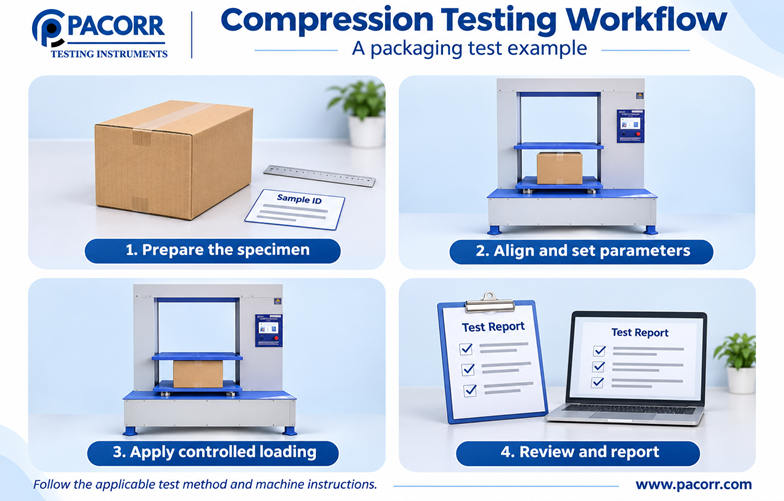
The following sequence explains the workflow. Operating settings must come from the applicable test method and machine instructions.
- Define the result needed. Identify the material, specimen geometry, standard, loading orientation and acceptance requirement. Decide whether the output is peak force, strength, stress at a defined strain or another property.
- Prepare and identify specimens. Measure the required dimensions, record the sample identity and complete the specified conditioning or curing. Prepare loading faces as required by the method.
- Check the measurement system. Confirm suitable calibration or verification over the intended range. Inspect fixtures, platens, guards, travel limits and relevant sensors before operation.
- Install and align the specimen. Use the correct fixtures and centre the specimen on the loading axis. Misalignment can introduce bending or uneven contact.
- Enter method-specific settings. Set the required rate, initial-contact or preload procedure, measurement channels and stopping condition. Crosshead speed, stress rate and strain rate are not interchangeable settings.
- Apply the test loading. Follow the prescribed sequence while the equipment records the available measurements. Keep clear of moving parts and use appropriate fragment containment for specimens that may shatter.
- Unload and examine the outcome. Follow the machine's unloading procedure before accessing the specimen. Record unusual behaviour such as slipping, buckling or an unexpected failure pattern.
- Review and report. Check calculations and validity before comparing results with the specification. Keep the specimen dimensions, conditioning, method, settings, units and failure observations with the result.
A result without its test conditions can be difficult to reproduce or compare, even when the displayed value looks precise.
Compressive strength calculation and result interpretation
For a method that defines compressive strength using peak load and original loaded area:
Compressive strength (MPa) = Peak compressive force (N) ÷ Loaded cross-sectional area (mm²)
The units work because 1 N/mm² = 1 MPa. The area must be expressed in square millimetres, not millimetres.
Worked example
Consider a hypothetical solid specimen with a square loaded face measuring 100 mm × 100 mm. Assume the applicable method uses peak force, and the recorded value is 250 kN.
| Step | Calculation | Result |
|---|---|---|
| Loaded area | 100 × 100 | 10,000 mm² |
| Convert force | 250 × 1,000 | 250,000 N |
| Calculate strength | 250,000 ÷ 10,000 | 25 MPa |
This illustrates the arithmetic, not a prescribed specimen size or acceptance threshold. Whether 25 MPa is acceptable depends on the material, method and specification.
For a circular loaded face, calculate the appropriate area from its measured diameter. If the method defines a property at a particular deformation or yield condition, use that definition rather than substituting peak force.
Why a graph is not automatically a stress–strain curve
A load–displacement graph plots measured force against measured movement. A stress–strain curve additionally requires appropriate specimen dimensions and valid strain measurement.
Crosshead movement can include deformation of the machine and fixtures. For modulus work, this can materially affect the result. Instron's ISO 604 guidance explains the importance of suitable strain measurement and correction for machine compliance when using relevant displacement-based methods.
For a carton, peak compression force normally describes the assembled package's resistance under the chosen procedure. Dividing it by the box footprint does not automatically produce a standardized material-strength value or a safe warehouse stacking limit.
Which compression testing standards apply?
Choose the standard by specimen and intended property. These examples cover different applications:
| Application | Relevant reference | Scope to check |
|---|---|---|
| Concrete cylinders and drilled cores | ASTM C39/C39M | Compressive strength of cylindrical concrete specimens |
| Hardened concrete in Indian testing programmes | IS 516, Part 1/Section 1:2021 | Compressive, flexural and split tensile strength methods |
| Rigid plastics | ASTM D695 | Compressive properties within the method's material scope |
| Applicable rigid and semi-rigid plastics | ISO 604 | Compressive behaviour and properties under defined conditions |
| Metals at room temperature | ASTM E9 | Axial compression testing of metallic materials |
| Shipping containers and unit loads | ASTM D642 | Compression resistance of packages and related components |
| Low-density flexible cellular materials | ISO 3386-1:2025 | Compression stress–strain characteristics within its density scope |
Use the edition and amendments required by the project or quality system. A standards reference on a product page does not, by itself, establish that a particular configuration, specimen and procedure meet every requirement.
Compression testing machine price in India
Compression testing machine prices depend on the application and supplied configuration. A packaging tester, a high-capacity concrete CTM and a UTM with strain accessories are different purchasing specifications.
As checked on 4 November 2026, the Pacorr Box Compression Tester page lists an approximate range of ₹1,20,000 to ₹5,50,000. This range applies specifically to box compression testers; obtain a quotation for the required model and options.
| Equipment category | Useful pricing approach |
|---|---|
| Box compression tester | Use the published category range as an initial reference, then confirm capacity, platform size and features |
| Concrete CTM | Request a quotation against the specimen, required force and applicable method |
| UTM configured for compression | Request an itemized quotation covering the frame, load cell, fixtures, sensors, controls and software |
The quotation should state whether GST, delivery, installation, training, calibration documentation and accessories are included. Compare equivalent configurations before comparing totals. A lower initial price can omit a measurement accessory or reporting function needed for the intended test.
How to choose a compression test machine
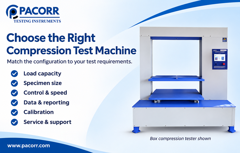
Begin with a written application brief: material, specimen dimensions, expected force, test method and required outputs. Then assess the following points.
Force range and measurement performance: Select sufficient capacity while checking accuracy and resolution at the forces actually used. Ask whether accuracy is stated as a percentage of reading or full scale. A large capacity number alone does not demonstrate suitability for low-force testing.
Test space and fixtures: Check platen dimensions, usable height, access, travel and fixture compatibility. Allow for the complete test setup rather than matching only the nominal specimen size.
Control and endpoints: Confirm the required speed range, control mode, preload sequence and stopping conditions. Verify a load-holding requirement explicitly; retaining a peak reading is a different function.
Data and reporting: Ask for a sample report showing units, specimen identification, settings and the actual graph type. Check storage, export formats and connectivity. Pacorr's Universal Testing Machine with Screen is described for packaging compression applications with load–distance reporting and Ethernet transfer. Confirm suitability and supplied features for your specimens.
Calibration and support: Request documentation covering the required measurement range and channels. ISO 7500-1 addresses static force-system calibration and verification for applicable uniaxial testing machines; strain, displacement and other measurements may need separate verification. Also establish service availability, installation needs and operator training.
Where possible, assess a representative sample on the proposed configuration and review the resulting report before ordering.
Common errors that can change the result
| Error | Why it matters | Practical response |
|---|---|---|
| Off-centre specimen | Introduces uneven loading or bending | Check alignment and fixture positioning |
| Unsuitable loading faces | Changes how force enters the specimen | Prepare surfaces as the method requires |
| Inconsistent conditioning | Makes comparisons unreliable | Record and control the relevant conditions |
| Incorrect rate or endpoint | Can change the reported property | Use the specified control variable and criterion |
| Buckling or barreling | Complicates material-property interpretation | Review geometry, fixtures and method validity |
| Crosshead travel treated as specimen strain | Can distort stiffness calculations | Use suitable strain measurement or permitted corrections |
| Inappropriate force range | May weaken measurement performance | Verify performance within the working range |
Keep kg and kgf distinct: kg describes mass, while kgf is a force unit. Retain the correct units during data entry, conversion and reporting.
Frequently asked questions
Does every compression test continue until the specimen breaks?
No. A test may stop at a specified force, deformation or other method-defined condition. Some materials deform extensively without a clear fracture. The endpoint must match the property being measured.
Can one CTM test concrete, cartons and plastics?
Only if its configuration meets each application's requirements. Differences in force range, platen size, control, fixtures and measurement can make separate machines more appropriate.
Is a hydraulic CTM always more accurate than an electromechanical machine?
No. Accuracy depends on the measurement system, calibration, working range and test setup. Select a machine against verified performance requirements rather than the drive label alone.
How often should a compression testing machine be calibrated?
Use an interval established by the applicable method, quality system, manufacturer guidance and service history. Overload, repairs, relocation or suspect readings may require additional verification before testing resumes.
Can a box compression result determine a safe stacking height?
It can inform an assessment, but it is insufficient by itself. Storage duration, humidity, load distribution, support conditions and package contents can affect stacking performance.
What information is needed for an accurate machine quotation?
Provide the specimen material and dimensions, expected load range, applicable standard, required control and endpoints, reporting needs and installation location. Include any special fixtures or strain measurements.
Conclusion
A compression test machine is useful when its loading system, measurement capabilities and test method match the specimen. The important decision is not simply how much force a machine can apply, but whether it can produce the result needed for a reliable quality or design decision.
Use the diagram to understand the load path, distinguish package resistance from material strength, and compare equipment against a clear application brief. For packaging compression requirements, share your specimen dimensions, expected force and reporting needs with Pacorr to discuss a suitable configuration and quotation.