
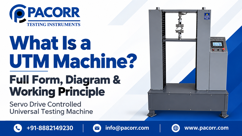
A UTM machine, or Universal Testing Machine, measures how a material responds to controlled mechanical loading. It applies a pulling or pushing force while recording force and movement. With suitable fixtures and measurement accessories, it can evaluate tensile strength, compression behaviour, elongation and other mechanical properties.
Two materials can look identical yet behave very differently when stretched, compressed or bent. For manufacturers, that difference can affect material selection, production consistency and whether a component meets its specification. A UTM helps turn those differences into measurable results.
This guide explains the UTM full form, its main parts, a typical machine arrangement, its working principle and how to interpret the results without confusing breaking force with material strength.
What Is the Full Form of UTM?
UTM stands for Universal Testing Machine. The word “universal” refers to its ability to support different mechanical tests using suitable grips, fixtures and control settings.
You may also encounter the term “universal tensile testing machine.” Tensile testing is a common application, but the broader term includes other supported loading arrangements. A machine does not automatically perform every test simply because it is called a UTM: its load capacity, accessories, control system and measurement equipment determine what it can do.
UTM Machine Diagram: Main Parts and Arrangement
The labelled diagram below shows a simplified twin-column electromechanical UTM arranged for a tensile test. The specimen sits between two grips. The moving crosshead changes the grip separation, and the load cell measures the force transmitted through the specimen.
Physical Components of a Universal Testing Machine
| Component | Function | Why it matters |
|---|---|---|
| Load frame | Supports the loading assembly and resists the test forces. | Frame stiffness and alignment influence measurement quality. |
| Moving crosshead | Moves the attached grip or fixture. | Provides the travel needed to deform the specimen. |
| Load cell | Converts applied force into a measurable signal. | Must have an appropriate calibrated range for the expected loads. |
| Grips and fixtures | Hold, support or load the specimen. | Incorrect fixtures can cause slippage, crushing or unintended bending. |
| Drive system | Produces controlled movement. | Electromechanical systems use a motor and screw mechanism; hydraulic systems use hydraulic actuation. |
| Displacement measurement | Tracks crosshead or actuator movement. | Provides machine movement data, which is not always equal to specimen extension. |
| Extensometer | Measures deformation over a defined gauge length. | Supports direct strain measurement where the method requires it. |
| Controller and software | Manage the test and process measurement data. | Apply the selected settings and calculate results from the correct inputs. |
What Is the Working Principle of a UTM Machine?
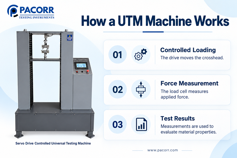
A UTM works by applying controlled mechanical loading to a specimen and measuring its response. The drive moves a grip or fixture, the load cell measures force, and displacement or strain sensors measure deformation. Software combines these readings with specimen dimensions to calculate the required properties.
In a tensile test, the grips move apart to stretch the specimen. In a compression test, platens move towards one another to compress it. A bending test uses a loading nose and supports to create a specified flexural arrangement.
In a servo-driven electromechanical system, feedback helps regulate motor operation to follow the selected command. Crosshead-speed control, force control and direct strain control are different capabilities; the available control modes depend on the equipment and sensors.
A UTM does not have to run until the specimen breaks. A method may end at a specified deformation, load or other stopping condition. For example, a compression procedure may require the force at a defined amount of deformation rather than a fracture load.
How a Typical Tensile Test Is Performed
- Select the method. Identify the material, required property and applicable test procedure before choosing settings.
- Prepare and condition the specimens. Follow the specified geometry, sampling direction and environmental conditions.
- Measure the relevant dimensions. Record width, thickness or diameter, along with the required gauge length. Incorrect dimensions produce incorrect stress or strain calculations.
- Fit the correct load cell and grips. Check that the specimen, fixtures and expected force are within the system’s working limits.
- Align and secure the specimen. Avoid unintended bending, uneven gripping pressure and damage during clamping.
- Set the test controls. Enter dimensions, speed or control rate, preload if required, and the stopping condition. Attach the specified strain-measurement device.
- Run and inspect the result. Review the curve and failure location. Investigate slippage or grip-related failure before accepting the result, then test the required number of specimens.
For a material-specific explanation, see Pacorr’s guide to testing the tensile strength of plastics using a universal testing machine.
Which Tests Can a UTM Perform?
| Test | Loading arrangement | Typical purpose |
|---|---|---|
| Tensile | Pulling between grips | Evaluate strength and extension under tension. |
| Compression | Loading between platens | Measure response to squeezing or crushing. |
| Flexural | Bending over supports | Evaluate bending strength or stiffness. |
| Peel | Separating bonded layers at a specified angle | Evaluate an adhesive or laminate bond. |
| Shear | Loading through a dedicated fixture | Evaluate resistance to relative sliding or shearing. |
| Tear | Pulling a specimen with prescribed geometry | Evaluate resistance to tear propagation. |
Each test needs its own specimen preparation, fixture arrangement and calculation method. A tensile result cannot substitute for a compression or flexural result. The same material may behave very differently under each loading mode.
How Are UTM Test Results Calculated?
The machine measures signals such as force and displacement. Properties such as stress and strain require additional information about the specimen.
Engineering strain: ε = ΔL / L₀
Percentage elongation: (ΔL / L₀) × 100
Here, F is force, A₀ is original cross-sectional area, L₀ is original gauge length, and ΔL is the change in that gauge length. When force is in newtons and area is in square millimetres, stress is in N/mm², equivalent to MPa.
Worked Example: Breaking Force Versus Tensile Strength
Consider an illustrative rectangular specimen with a measured width of 10 mm and thickness of 4 mm. Its original cross-sectional area is 40 mm². If its maximum tensile force is 2,000 N, its maximum engineering stress is:
2,000 N ÷ 40 mm² = 50 MPa
This is a calculation example, not a Pacorr test result or an acceptance limit. A specimen with twice the cross-sectional area could carry more force without having a higher material strength. That is why maximum load and tensile strength should not be used interchangeably.
Other useful results include yield behaviour, elongation at break and modulus. Their determination depends on the material, measurement system and method. The maximum force may occur before final fracture, so maximum load and break load can also differ.
Why Crosshead Travel Is Not Always Specimen Strain
Crosshead movement can include deformation of the machine and grips, specimen seating and grip slippage. Dividing that movement by gauge length does not automatically produce an accurate material strain.
An appropriate extensometer measures deformation over a defined region of the specimen. This distinction is particularly important when determining stiffness or small-strain properties. Select the measurement approach required by the test method rather than assuming every software-generated strain value has the same basis.
Test Standards and Reliable Measurements
Choose the standard for the material and property being measured. Common tensile-test references include ASTM D638 for plastics, ASTM D882 for thin plastic sheeting, ASTM D412 for rubber and elastomers, and ISO 6892-1 for metallic materials at room temperature. These methods are not interchangeable.
Use the applicable current edition to establish specimen preparation, conditioning, test rate, measurement requirements and reporting. A machine’s ability to accept a specimen does not by itself demonstrate compliance with a standard.
Calibration also needs to match the measurements used. Force verification does not automatically verify extensometer accuracy, crosshead displacement or test speed. Keep calibration records and investigate unexpected changes in results. Pacorr’s working principle and calibration guide provides related reading.
Common Mistakes That Affect UTM Results
- Using unsuitable grips: slippage or local crushing can change the apparent response.
- Entering nominal dimensions: measured specimen dimensions should be used where the method requires them.
- Changing speed between batches: rate-sensitive materials may give different results even when their composition has not changed.
- Ignoring specimen direction: film, sheet and textile properties can depend on sampling orientation.
- Accepting every fracture location: failure near a grip may require investigation under the selected method.
- Comparing incompatible reports: results from different conditioning, geometry or procedures may not be directly comparable.
A useful report identifies the material, specimen dimensions, method, test settings, measurement approach and individual results. Record unusual behaviour so that future comparisons have enough context.
How to Select a UTM Machine for Your Application
Start with the specimens and the measurements you need. Choosing only by the largest available force capacity can overlook low-force sensitivity, available travel or fixture compatibility.
| Selection factor | What to establish |
|---|---|
| Force range | Expected minimum and maximum loads, with suitable capacity and calibrated measurement performance. |
| Testing space | Specimen length, fixture height, width clearance and extension before the stopping point. |
| Speed and control | Required rate range and whether the method specifies crosshead, force or strain control. |
| Grips and accessories | Material thickness, surface condition, loading mode and strain-measurement needs. |
| Reporting | Required curves, calculations, traceability and data export. |
If your work is limited to pulling tests, compare the actual capabilities of a dedicated tensile tester with a configurable UTM. Pacorr’s tensile testing machine versus universal testing machine guide explains the distinction.
Pacorr Servo Drive Controlled Universal Testing Machine
Pacorr’s Servo Drive Controlled Universal Testing Machine uses an AC servo motor, servo drive and ball-screw mechanism. Its listed features include real-time graphical results, interchangeable fixtures, automatic report generation, overload protection, travel limits and an emergency stop.
The system can be configured for tensile, compression, bending, peel, tear and shear applications. Capacity, testing space, speed and accessories should be confirmed against the intended specimen and method. When requesting a configuration, provide the material, specimen dimensions, expected force range, required tests and reporting needs.
Frequently Asked Questions About UTM Machines
What is a UTM machine used for?
A UTM is used to evaluate mechanical behaviour under controlled loading. Applications include material comparison, production quality control and product development. The results depend on the test arrangement and measurement method.
What is the difference between UTM and UTS?
UTM means Universal Testing Machine, the equipment used for testing. UTS means ultimate tensile strength, a property generally expressed as the maximum engineering tensile stress reached during a tensile test.
Can the same UTM perform tensile and compression tests?
Yes, if the machine supports both modes and has appropriate fixtures, measurement capacity and software. Tensile grips hold a specimen for pulling; compression platens apply compressive loading.
Does a UTM directly measure tensile strength?
The load cell measures force. Tensile strength is calculated using force and the specimen’s original cross-sectional area, according to the selected method. Accurate dimension measurements are therefore essential.
Is a servo-controlled UTM the same as a hydraulic UTM?
No. “Servo-controlled” describes a feedback-control approach; “hydraulic” describes an actuation technology. Both electromechanical and hydraulic machines can use servo control. Pacorr’s product discussed here uses an AC servo motor and ball-screw drive.
What determines the price of a UTM machine?
Price depends on capacity, control capabilities, fixtures, strain-measurement accessories, software and service requirements. An application-specific quotation is more useful than a price that does not identify what is included.
Conclusion
A Universal Testing Machine helps explain how a material carries load and deforms. Understanding its components and working principle is the first step; selecting suitable fixtures, measuring dimensions correctly and following the right method are what make the results meaningful.
For a laboratory planning tensile, compression or related mechanical testing, explore Pacorr’s servo drive controlled UTM. Share your specimen details and testing requirements to identify a configuration suited to the measurements your quality-control process needs.
Recent Blogs
Enhance your understanding of testing and precise quality control indistinct applications with our
knowledge based articles coming from top editors of industry leaders.
Our USP's
Demonstration of Machine
- Try Before You Decide
- Experience Before You Invest
- See It in Action – Free Demo
Global Reach
- Delivering Excellence Worldwide
- Serving Across Borders
- Your Global Supply Partner
On-Site Support
- Support That Comes to You
- On-Ground Assistance, Anywhere
- We Reach Where You Are
Team Strength
- Powered by Expert Minds
- Driven by Skilled Professionals
- Engineering Excellence Team
Manufacturing
- Precision-Driven Manufacturing
- Smart & Automated Production
- Engineered In-House Excellence
