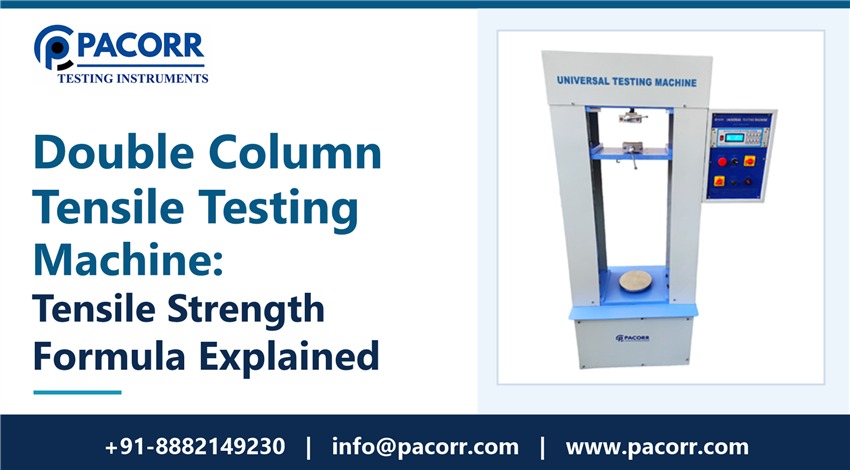
A double column tensile testing machine pulls a prepared specimen between two grips and records the force required to stretch it. The basic tensile strength formula is ultimate tensile strength = maximum valid tensile force ÷ original cross-sectional area. Enter force in newtons and area in square millimetres to obtain megapascals. For example, a specimen with an original area of 40.00 mm² and a peak load of 2,720 N has a tensile strength of 68.0 MPa.
The formula is short. The most consequential decisions are which specimen to test, how to measure its area and which event in the force record to use. A report might show a peak force, a yield result and a breaking force for the same specimen. They answer different questions. This guide explains those differences, works through flat and round examples and shows what to verify when setting up or buying a machine. Its workflow is educational. Use the controlled test method and instrument instructions for actual specimen dimensions, settings and acceptance rules.
What is a double column tensile testing machine?
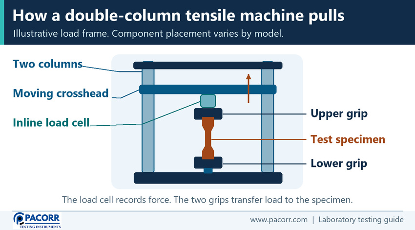
A double column tensile testing machine is a load frame with two uprights supporting or guiding a moving crosshead. The specimen sits between opposing grips. The drive moves the crosshead, the load cell measures applied force and the control system records force with time and the selected displacement or extension signal. If the method requires strain measured over a defined specimen span, the system also needs an appropriate extensometer or another permitted means of measuring that extension.
| Component | Role in a tensile test |
|---|---|
| Frame and crosshead | Support the load train and apply controlled movement. Specimen space depends on the installed fixtures and their position. |
| Load cell | Measures tensile force over its verified working range. The frame and cell have separate capacities. |
| Upper and lower grips | Transfer force to the specimen with appropriate alignment and limited slip or grip damage. |
| Extensometer, when required | Measures the change in length over a defined span of the specimen. |
| Controller and software | Manage the test sequence and record raw signals. The selected calculation and event rules determine reported properties. |
Where does a two-column frame help?
Start with the specimens and methods the lab actually runs. A plant testing machined metal coupons may need headroom for higher peak forces, robust grips and dependable low-strain measurements. A plastics laboratory might use interchangeable cells and jaw faces for rigid moulded coupons and thin films. A long-extension material can make grip separation and available travel as important to selection as force capacity. Two uprights describe the machine architecture. The capacity and usefulness of a complete test setup depend on the frame, fixtures, cell, specimen space and verified measuring ranges.
If the workload includes compression, bending or other tests, ask separately which fixtures, space and software procedures are supplied for each. Check the Pacorr universal test frame overview and Pacorr tensile testing machine range when comparing application needs.
What is the tensile strength formula in MPa?
For a method that reports engineering stress at maximum force, calculate UTS = Fmax ÷ A₀. Fmax is the maximum valid tensile force for that specimen within the applicable test record. A₀ is the original cross-sectional area of the specimen's test section. For an engineering stress curve, calculate the stress at each force sample F by dividing F by the same A₀.
| Input or output | Working units and meaning |
|---|---|
| Fmax | Maximum valid test force, in N. Multiply a value in kN by 1,000. |
| A₀ | Original cross-sectional area, in mm². Use pre-test measurements and the area rule in the test method. |
| UTS | Maximum engineering tensile stress. One N/mm² equals one MPa. |
The units check is a useful first audit. A newton is a force. A newton per square millimetre is a stress. A report reading 2.72 kN gives the force on that specimen, while 68.0 MPa describes the result after dividing by its area. A test may report a force or a force per unit width for some products or constructions. Confirm the property and its units from the governing method before applying an area-based formula.
How do you calculate the original cross-sectional area?
Measure the section that resists the pull, in a plane perpendicular to the specimen axis. For a rectangular section, A₀ = w₀ × t₀, where w₀ is the original width and t₀ is the original thickness. For a solid circular section, A₀ = π × d₀² ÷ 4, where d₀ is the original diameter. The width of a dog-bone specimen belongs to the narrowed test section used by its method. The wide ends are for gripping. For a round specimen, keep diameter and radius distinct in the worksheet.
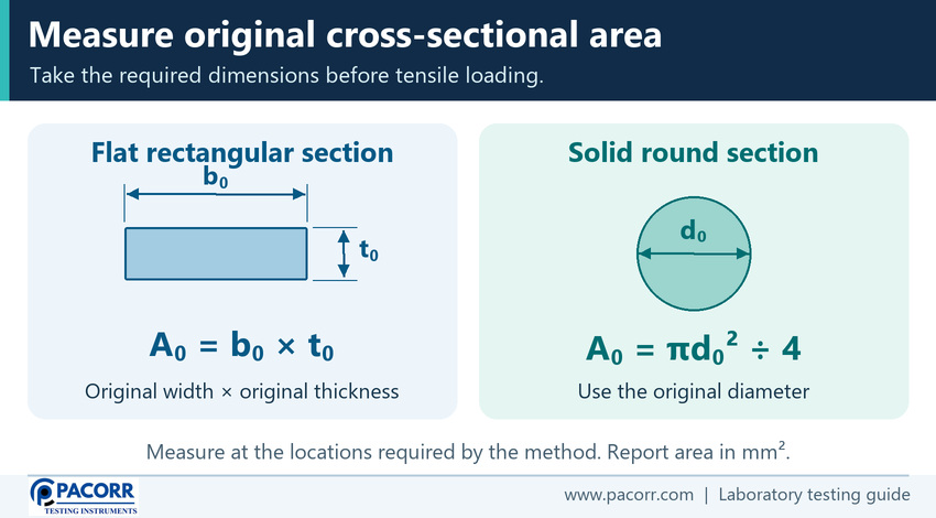
Follow the method's instructions on measurement locations, number of readings, contact force, rounding and selection of a value from those readings. Thin film can be sensitive to the thickness measurement system. Round stock can be out of round. For tubes, stranded cables, coated sections or other non-solid specimens, the governing method must define how to express the result and which area, if any, to use. The solid-circle equation applied to a hollow tube would count the hole as load-bearing material.
How do you calculate tensile strength for a flat specimen?
In this flat-specimen example, the recorded original width is 12.50 mm and thickness is 3.20 mm. The maximum valid force is 2.72 kN. The dimensions, force and results are illustrative.
- Calculate the area using 12.50 mm × 3.20 mm to obtain 40.00 mm².
- Convert the peak force from 2.72 kN to 2,720 N.
- Divide 2,720 N by 40.00 mm² to obtain 68.0 MPa.
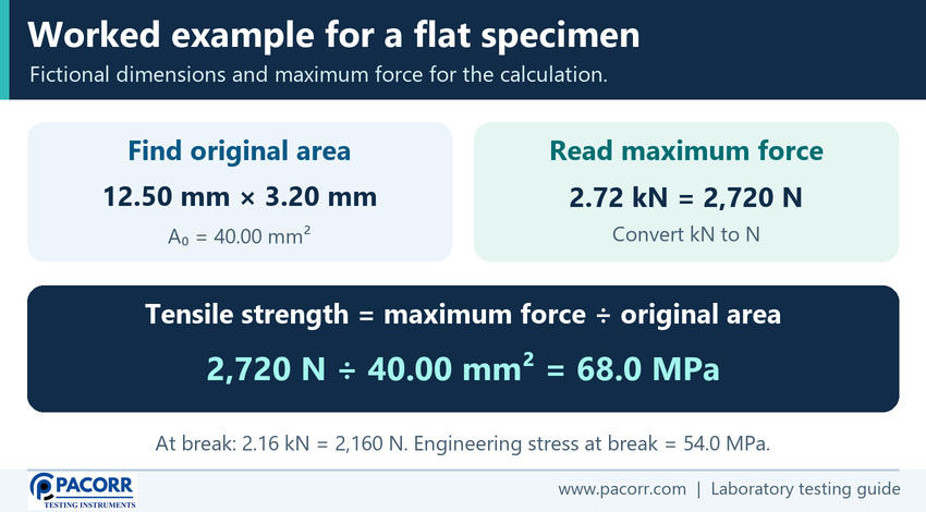
If this same illustrative specimen breaks later at 2.16 kN, the engineering stress at that break event is 54.0 MPa using the same original area. The tensile strength remains 68.0 MPa. The calculation uses the force identified as the break event by the method rather than a zero-force point recorded after complete fracture. Record the force source alongside the result so someone reviewing the test can reproduce the calculation.
How do you calculate tensile strength for a round specimen?
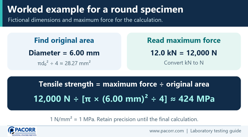
Consider a solid round specimen with an original measured diameter of 6.00 mm and peak force of 12.0 kN. Use the circular cross-section perpendicular to the pull axis. This is a second illustrative calculation, with no implied method dimensions or instrument settings.
- Square 6.00 mm to obtain 36.00 mm².
- Multiply by π and divide by four to obtain A₀ ≈ 28.27 mm².
- Convert 12.0 kN to 12,000 N. Divide by the unrounded area to obtain about 424.4 N/mm², or 424 MPa to three significant figures.
The diameter is squared, so area errors can grow faster than the underlying diameter error. If a spreadsheet uses 6.10 mm when the actual recorded diameter was 6.00 mm, the calculated area is about 3.36% higher. At the same force the reported stress is about 3.25% lower. This check is particularly useful when an old dimension is copied to a new specimen record or when mixed diameters are analysed in one batch. Keep extra precision during the calculation and apply the method or reporting policy at the end.
What is the difference between peak load, yield and break?
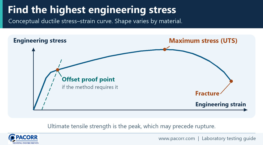
Each term identifies a different feature of the test. Peak load is a force. Engineering tensile strength expresses the peak as stress. Yield results describe a material response determined by the chosen method. Break measurements relate to the event at fracture. A ductile metal coupon can neck and break at a lower force than its earlier peak, while another material can break near its maximum force. The shape alone does not determine whether an event is valid.
| Property | What to read or calculate |
|---|---|
| Peak load | The maximum valid tensile force, normally reported in N or kN. |
| Ultimate tensile strength | Peak force divided by the original cross-sectional area, for an area-based engineering result. |
| Yield or proof strength | The stress obtained from the yield criterion or the specified offset procedure in the applicable method. |
| Engineering stress at break | The method's break-event force divided by original area, where this property is reported. |
| Elongation or strain | A change in length expressed using the reference length and procedure for that property. |
Some methods define distinct upper and lower yield strengths. Others specify a proof or offset criterion for materials without a clear yield event. For example, if the material specification calls for a 0.2% offset, its construction uses a 0.002 strain offset on a fractional-strain axis and a line parallel to the relevant elastic slope. Use the method's slope and event rules. A preset yield label or the first visible bend on a curve is insufficient to establish the property. Where strains localise after necking, true stress requires an instantaneous area appropriate to the point considered. The measured area after fracture cannot replace the original area in the UTS formula.
When do you need an extensometer?
Engineering strain is ε = ΔL ÷ L₀, where L₀ is the defined original gauge length and ΔL is its change. If a 50.0 mm original gauge length extends by 2.50 mm, the engineering strain is 0.0500, or 5.00%. These numbers are illustrative. The method determines the reference length, the measurement arrangement, the event at which strain is read and the precision needed.
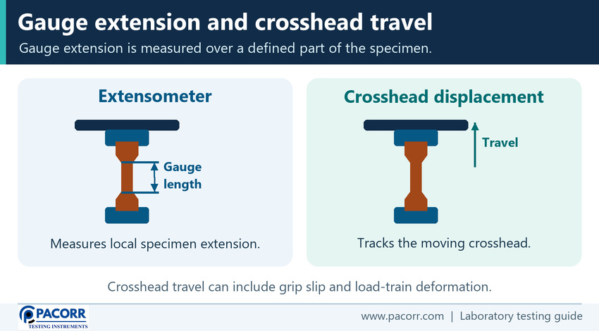
Crosshead travel is measured on the machine. It can include fixture and frame deformation, seating of jaw faces, grip slip and stretch outside the gauge span. An extensometer follows the specimen over its own defined span. These readings can diverge even when the sensor and drive are functioning normally. Modulus and offset-proof strength especially depend on reliable small-strain data. For large extensions, also check sensor range and how the method treats removal, handover or alternative measurement channels. Some thin-sheet procedures allow specified extension measurements based on grip separation, among other options. Record which option was used. A metal method's post-fracture elongation measured between marks is a separate result from an extensometer value at the instant of fracture.
How do you choose grips and check alignment?
Choose the mounting system for the specimen material, dimensions, surface and expected force. A rigid flat coupon can need different faces and clamping behaviour from a film strip. A round bar may need shaped jaws or another appropriate fixture. Check the tensile-axis alignment through both grips, and confirm that a specimen can be inserted evenly with the required engagement. Misalignment adds bending and can change where failure starts. Excessive local clamping pressure can cut or crush a specimen, while insufficient grip can let it slide.
Assess strain measurement after choosing the grips. Check that a contact sensor can attach at the required span without colliding with the jaws, and that an optical sensor can track the targets through the required extension. If the installation requires different grip sets, verify their combined ratings, compatibility with the adapters and remaining separation at the end of a test. Those constraints affect a purchase even when the required peak force fits easily within the frame rating.
Which tensile test standards apply to metals, plastics and films?
Choose the method from the material specification and the property the report needs to support. A machine's ability to pull a specimen confirms only part of the setup. The test needs the specified specimen and apparatus, conditioning, rate control, measuring ranges and calculations. The following are common routes.
| Specimen or material | Methods to check | Scope distinction |
|---|---|---|
| Machined metallic coupon, bar or other approved metal form | ASTM E8/E8M or ISO 6892-1 | Room-temperature testing of metallic materials. Confirm permitted geometry, gauge length and rate control. |
| Moulded or machined plastic specimen | ASTM D638 or the applicable part of ISO 527 | D638 covers standard dumbbell-shaped specimens for reinforced and unreinforced plastics within its scope. ISO 527-2 covers moulding and extrusion plastics. |
| Thin plastic film or sheeting | ASTM D882 or ISO 527-3 | ASTM D882 and ISO 527-3 cover material below 1 mm within their defined scopes. Check allowed extensions, specimen orientation and method-specific settings. |
ASTM E8/E8M's public scope notes different gauge lengths for most round specimens under E8 and E8M. Consult the actual specimen drawing and units called for in the contract. ASTM D638 covers material up to 14 mm thick as described by its scope and identifies D882 as preferred for film or thin sheet below 1.0 mm. A film strip, a moulded coupon and a specimen containing a seal or bond can require different procedures. The term tensile test alone does not establish which reported quantity applies. ASTM E8/E8M, ASTM D638 and ASTM D882.
For more detail on film and moulded specimen selection, see Pacorr's ASTM D638 versus ASTM D882 comparison and the guide to mechanical tests on films and laminates. For a rubber, textile, wire assembly, composite or bonded product, check its own method and test definition before adopting one of the routes above.
What is the difference between crosshead speed and strain rate?
Crosshead speed describes machine movement and is commonly expressed in mm/min. Strain rate describes how quickly the specimen's strain changes and can be expressed in s⁻¹. If elongation were uniform across a 50 mm span and all 5 mm/min of crosshead motion appeared across that span, the estimated strain rate would be 0.10 min⁻¹, about 0.00167 s⁻¹. Real tests can depart from the assumptions because the load train deforms, deformation extends beyond the measurement span or the material necks. Treat the conversion as an illustration.
Select the control mode and rates from the controlled method. If the method specifies changes between stages, identify the transition trigger, set the required values and keep those settings in the test record. Verify the machine can perform at the required rates with the cell and grips installed. Temperature, rate and moisture can affect a polymer result. Comparing a data sheet value to a production result requires checking the test conditions before treating a difference as a material problem. ISO 6892-1 room-temperature metal tensile test scope.
What is a defensible tensile testing procedure?
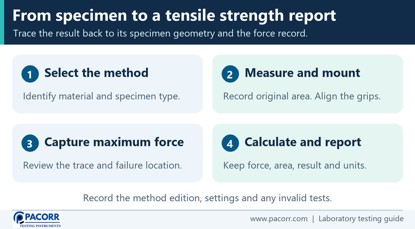
Use this bench workflow to plan the test and review the result. Setup steps, conditioning, specimen quantities, safe travel and report fields should come from the controlled method, local procedure and instrument instructions.
- Identify the sample, batch, source direction and test method edition. Determine whether the report calls for maximum stress, yield or proof strength, modulus, extension or multiple outputs.
- Prepare and condition the prescribed specimens. Keep machining marks, cutting defects, labels and handling damage away from the measured test region as applicable. Measure and record each specimen's original dimensions separately.
- Fit the verified load cell and rated grips. Select the length channel and check the system's required starting condition. Verify alignment, grip clearance, force and travel limits and the control programme.
- Install the specimen centrally and attach or configure the required extension system. Set zero references and apply any prescribed preload in the sequence specified by the method. Record conditions that affect interpretation.
- Run the selected control programme. Retain the raw force and extension channels with enough detail to identify the required events. Check for slip, sudden signal changes, overload, early stopping and fracture location.
- Apply the method's validity rules. Calculate each accepted result using the specimen's own area and the required force event. Record deviations, excluded results and repeated tests with their reasons.
How do you size the load cell and working range?
Estimate the force using Fmax ≈ expected engineering tensile strength × original area. This reverses the UTS equation for planning. For example, a solid round 6.00 mm specimen expected to reach 500 MPa would require about 500 N/mm² × 28.274 mm² = 14.1 kN near its peak. Allow for the strongest material and largest section in the real workload, including plausible variation. Compare this with the ratings of the frame, sensor, grips and adapters and with any method or safety requirements. This estimate is separate from the earlier measured-force example.
Next, consider the smallest meaningful forces. A 12 mm × 0.060 mm illustrative film strip at 45 MPa would peak near 32.4 N. A frame selected for a demanding metal test can physically accommodate the film while its installed load cell may be poorly suited to that low-force region. Request the verified force range and the uncertainty or classification needed for the method at the actual loads of interest. A second cell and film grips may make financial and technical sense for a mixed-specimen lab. Resolution describes the smallest reporting or display increment. It does not establish total measurement uncertainty, force verification or an acceptable minimum working force.
Which errors can change the reported tensile strength?
| Observation | What to verify first |
|---|---|
| A tenfold or thousandfold change | Compare entered dimensions and force units with the original readings. In particular verify conversion from kN to N and thickness from µm to mm. |
| An unusually long extension before load rises | Look for seating, slack, grip slip or a mismatched zero reference. Check which channel supplied the strain calculation. |
| An unexpected sharp maximum | Inspect the raw data around the peak for a transient, grip movement or an overload. Check the valid event rules before recomputing. |
| Several failures near the same jaw | Check jaw face wear, pressure, alignment and specimen tack or cutting marks. Apply the governing invalid-result rule. |
| Film results change between rolls or directions | Check thickness at measured locations, extrusion or web direction, conditioning and the lot sampling plan. |
Do not decide that every grip-area break is automatically invalid across all methods. Record where and how the specimen failed, then apply the stated criterion. Re-running a valid low result until a preferred value appears undermines the lot record. If changing one machine parameter seems to solve scatter, document the change and test it with comparable material before combining the new values with the historical trend.
How should a laboratory report results and make acceptance decisions?
For each specimen, preserve its ID, dimensions and original area, maximum force, formula outcome, break location and validity status. Record the governing method and edition, specimen geometry and orientation, test and conditioning environment, machine configuration, rate programme and extension measurement details for the series. Include each property required by the specification with its units and method-specific definition. That information helps a second lab detect a genuine material difference rather than compare dissimilar tests.
Calculate stress separately for each specimen and summarise the individual results in the way the specification requires. If areas vary, dividing the mean force by the mean area can produce a different number from averaging stresses. Keep the raw values and let the applicable rounding rule govern the report. Decide acceptance using the linked material or customer specification, including any rule about minimum individual values, averages, allowable repeats or uncertainty. A tensile test method determines how to measure the property. It does not provide a universal acceptance limit for all materials.
What should the verification and maintenance plan cover?
Build the plan around force, extension and controlled movement. Inspect grip faces, fasteners and adapters for wear or damage and keep the relevant mounting surfaces clean. Check the usable travel, completion limits, force overload settings and the equipment checks required by the manufacturer's instructions and the laboratory's procedure. Retain calibration or verification evidence for relevant force ranges and the extension equipment actually used. ASTM E4 addresses force calibration and verification, and ASTM E83 addresses calibration, verification and classification of extensometer systems. The required classes, intervals and procedure depend on the method and quality system.
Maintain traceability when a cell, extension device, grip train or software template changes. Check a saved data set with a known answer after modifying a report template. Use a suitable reference or control sample to detect drift before routine batches are reviewed, where that approach fits the lab's procedure. A control sample helps monitor consistency. It does not replace calibration evidence for a measuring channel.
What does Pacorr publish for its double column tensile machine?
The Pacorr Double Column Tensile Testing Machine listing describes a double column system with capacity up to 50 kN and configurable options. The page lists PCTTM-5000D near the product heading and PCDCTTM-5000 in the specification block. Ask for the precise model identifier and written configuration for the offered machine. The following values are published listing details for initial screening.
| Published item | Pacorr listing value |
|---|---|
| Maximum load capacity | Up to 50 kN, with custom capacities mentioned. |
| Crosshead travel | 1,000 mm, described as customisable. |
| Crosshead speed | 0.5 to 500 mm/min, adjustable. |
| Load resolution | 0.01 kN, a published resolution value. |
| Display and power | Digital or touchscreen options, with 220 V AC, 50 Hz listed. |
Ask which speed and travel limits apply with the proposed grips and load cell, and whether the position called travel is different from usable specimen extension. Request the controller, data export, calibration documentation and accessory list in writing. Suitability for a named standard depends on the offered configuration, the specimen method and the operating conditions. A general equipment description alone does not establish it.
What determines the machine price and what should you ask for?
A price was unavailable on the verified listing. Request a quotation against your specimen types and properties. The quote can vary with frame capacity, load cells and verified force ranges, grips and adapters, extensometer, software and reporting modules, calibration scope, installation and service needs. For low-strain work, ask what the system can measure at the needed span and extension. For high-extension work, ask for usable travel with the actual fixtures and method.
Send the method and edition, sample drawings or photographs, original section dimensions and expected force range. If the breaking force is unknown, send representative specimens or specify the material and expected strength range so the setup can be reviewed. A useful demonstration returns the raw data and a sample report with force, area and property labels you can check. Ask for a configuration that covers the real test range, from the lightest meaningful force to the highest expected load.
Frequently asked questions
What is the tensile strength formula in MPa?
Divide the maximum valid tensile force in newtons by the original cross-sectional area in square millimetres. One N/mm² equals one MPa.
Why do I use the original area for ultimate tensile strength?
Ultimate tensile strength is an engineering stress based on the specimen's original cross-sectional area. An instantaneous area is relevant to a true stress calculation, while an area measured after fracture serves other measurements such as reduction of area where applicable.
What is the tensile strength formula for a round bar?
For a solid circular test section, divide the maximum force by π times the original diameter squared divided by four. Enter the force in newtons and diameter in millimetres to obtain MPa.
Is maximum load the same as tensile strength?
Maximum load is the peak force on a particular specimen, reported in N or kN. Tensile strength expresses that peak relative to the original area and can be reported in MPa.
Can tensile strength and engineering stress at break be different?
Yes. A specimen can reach its maximum force before fracture and then break at a lower force. Divide the applicable force for each property by the original area and label both results.
Can I use crosshead travel to calculate strain?
Use the extension measurement allowed by your test method. Crosshead travel can include machine deformation, jaw seating and slip. A suitable extensometer directly measures extension over its defined specimen span.
Can one double column machine test thin films and metals?
Potentially, if each configuration covers the necessary force and strain ranges, gripping, control and travel. A lab may need different load cells, grips and extension measurement arrangements for the two applications.
How do I choose a machine capacity if I only know the expected strength?
Multiply the expected engineering tensile strength in MPa by the original cross-sectional area in mm² to estimate peak force in newtons. Check the full anticipated range and choose cell and fixture ratings with suitable operating margin and verified force coverage.
Where do I find the pass limit for tensile strength?
Use the governing material specification, customer drawing, purchase requirement or approved quality plan. It should define the property, method and acceptance rule for the material or lot.
How can Pacorr help configure your tensile test?
Share the standard and edition, specimen dimensions, expected minimum and maximum forces and the outputs your quality team needs. Include gauge length and required extension or rate control where known. Ask Pacorr to confirm the offered model, load cell and verification range, grips, extension system, usable travel and report fields. Contact Pacorr for a configuration and quotation.