ASTM D638 and ASTM D882 both measure tensile behaviour, but they answer the question using different specimen systems. For plastic film and thin sheeting below 1.0 mm, D882 is normally the starting point. For a moulded plastic material evaluated with a standard dumbbell specimen, D638 is generally the relevant route. The product specification, specimen form and required property must support the final choice.
Choosing correctly matters because a plausible strength value can still come from an unsuitable test. A strip may slip without an obvious warning; an incorrect thickness can change the calculated stress; and crosshead travel can be mistaken for strain in the specimen. This guide explains the selection and the measurement decisions behind a defensible result. Procedures are educational workflows, not model-specific operating instructions or replacements for the controlled standards.
What is the quickest way to choose between D638 and D882?
Begin with the question being asked: are you characterising a film supplied on a roll, or a moulded material represented by a prepared coupon? Then check the applicable material or customer specification before cutting anything. Do not select the method simply because an existing machine has a familiar menu option.
| Your testing situation | Starting decision |
|---|---|
| Thin plastic film or sheet below 1.0 mm | Assess D882 and the product-specific requirements. |
| Moulded plastic represented by a standard dumbbell coupon | Assess D638, including the correct specimen type. |
| Plastic sheet at or above 1.0 mm | Review D638 suitability and the governing specification. |
| A seal, bonded interface, tear or complete component | Identify the property-specific method first. |
This table is a screening aid. Record the final method, edition, specimen geometry and required outputs in the test request. A supplier and buyer should agree these details before comparing certificates or establishing an acceptance limit.
What does ASTM D638 cover?
The official ASTM D638-22 scope covers unreinforced and reinforced plastics tested as standard dumbbell-shaped specimens under defined conditions. It addresses thicknesses up to 14 mm and directs thicker material towards machining; thin film below 1.0 mm is preferably tested using D882. Special materials can require another method.
For a moulding project, decide whether the coupon should represent resin qualification, a specific processing condition or material taken from a finished part. Those are different sampling questions. A separately moulded specimen may be convenient, yet it does not automatically reproduce a component's weld line, local fibre orientation or cooling history. Explain the connection between coupon and product in the report rather than implying that a material result certifies the entire component.
What does ASTM D882 cover?
The current official listing is ASTM D882-26a, covering thin plastic sheeting and film below 1.0 mm, including structures with inseparable layers or coatings. The public scope also recognises different ways of measuring extension. Both this edition and the D638 edition above were checked on 14 November 2026; use the edition required by your contract.
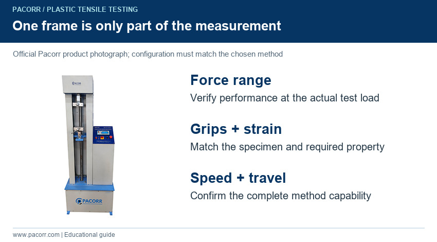
Film inspection commonly uses straight strip specimens. The practical challenge is to transfer force into a thin, flexible test piece without edge damage, twisting or slip. A film can stretch dramatically while carrying a modest force, so force capacity alone is a poor basis for choosing equipment. The usable travel, grip design and extension-measurement arrangement deserve equal attention.
How should the 1.0 mm boundary be interpreted?
Less than 1.0 mm means below 1,000 micrometres, not below 100 micrometres. Exactly 1.0 mm is not within the stated less-than range. A flexible sheet does not become a film-test specimen solely because it bends easily; thickness and product form must be considered together.
If measurements lie near a method boundary, retain the measured distribution and resolve the test specification before proceeding. Do not round a thickness down just to fit a preferred method. Similarly, do not stack several film layers to manufacture a thicker specimen: the resulting assembly has interfaces and gripping behaviour that differ from a single sheet. These are test-planning decisions to settle with the customer, not adjustments to make after seeing an inconvenient result.
How does selection work for real products?
Consider four illustrative requests. A 50 micrometre packaging film needs a film-oriented tensile assessment, with the roll direction identified. A 3 mm injection-moulded plaque needs an appropriate moulded-plastic coupon plan. A 0.8 mm multilayer flexible sheet requires clarity about whether the whole construction or a particular layer is being evaluated. A pouch opening test asks about a seal, even if its base material is plastic film.
In each case, write the measurand in plain language: maximum tensile stress of the intact web, yield behaviour of the moulded material, elongation of the construction, or force to separate a seal. That sentence prevents a surprising number of method-selection errors. It also tells the equipment supplier which fixtures and measurement channels are actually needed.
Why are a dumbbell and a film strip different?
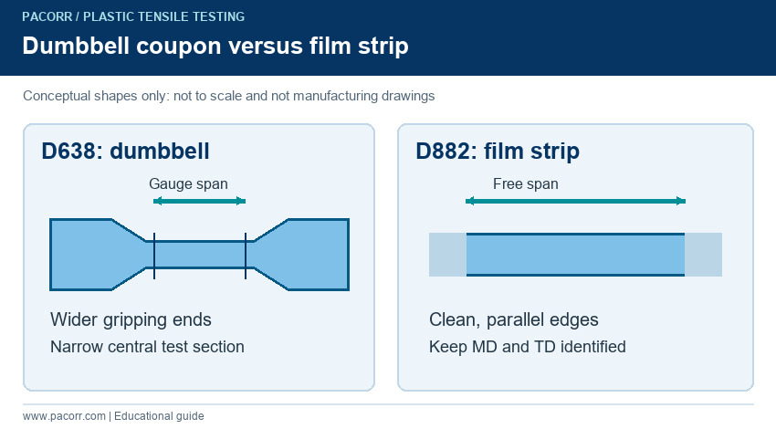
A dumbbell has wider gripping ends and a narrower central test section. Its transition regions help transfer the load into that section. A straight film strip has parallel sides across its test length, making cutting quality, alignment and grip behaviour particularly visible in the result. The accompanying diagram is conceptual and deliberately carries no manufacturing dimensions.
D638 specimen types are not interchangeable labels. Select the geometry required for the material, available thickness and purpose, then use its controlled drawing and tolerances. Likewise, take film-strip width, length and initial separation from the selected procedure. Copying dimensions from a photograph or from an unrelated resin datasheet can create a test that looks standardised but cannot be compared properly. Keep the cutting tool identity and specimen drawing revision with the work instruction.
How should specimens be prepared without introducing damage?
Prepare enough material to preserve orientation, location and traceability. Label the source sheet, roll or moulding before subdivision. Place identification outside the measured region, and avoid handling that stretches thin film. Inspect cut edges under suitable illumination: a nick can become the starting point of a premature tear.
For machined coupons, control heat, tool condition and finishing so that preparation does not introduce a different material state. For moulded coupons, record the relevant processing history. Do not sand, polish or repair a questionable specimen without a defined procedure. Keep rejected preparation pieces and their reasons separate from specimens rejected during a test. That distinction helps identify whether scatter originates in the material, the cutter or the machine setup.
Why is thickness measurement often the biggest film-testing risk?
Engineering stress uses the original cross-sectional area. For a rectangular section, that area is width multiplied by thickness. A modest absolute thickness error can therefore become a large percentage error for a very thin film. ASTM D6988-26 addresses thickness determination when the measurement is used to calculate film-test properties; it is not a substitute for the applicable tensile method's instructions.
Measure the specified locations with an appropriate instrument and contact arrangement. Avoid squeezing a compressible construction into an artificially small value. Enter specimen-specific dimensions where required rather than automatically applying the nominal roll label to every sample. As an illustrative sensitivity check, entering 0.045 mm instead of an actual 0.050 mm makes calculated stress approximately 11.1% too high at the same force and width.
Why must machine direction and transverse direction remain separate?
Machine direction, or MD, follows the web's production direction. Transverse direction, or TD, runs across the web. Stretching and processing can create directional behaviour, so a roll-average result that mixes MD and TD may hide information needed by a converter or packaging designer.
Mark direction before cutting and preserve it through data export. Describe sampling positions across the roll and along its length. For moulded parts, use meaningful orientation labels tied to flow, a feature or a drawing. Do not describe a difference as a material defect before checking whether the compared coupons represent different directions. A useful investigation keeps orientation, location and preparation as separate fields rather than embedding all of them in an ambiguous sample name.
What conditioning information should the laboratory record?
Temperature and moisture history can influence polymer behaviour. ASTM D618 provides conditioning practices for plastics and distinguishes reproducible conditioning from necessarily reaching full equilibrium. Apply the conditions and duration required by the governing procedure or material specification; there is no single conditioning recipe that can safely be assigned to every plastic in this article.
Record the specimen's initial state, conditioning environment, duration and test environment. For moisture-sensitive materials, clarify whether the request concerns a dry state, an agreed conditioned state or an as-received product. Keep transfer time and storage controlled where they matter. Comparing a recently dried coupon with one exposed to a different laboratory environment can confuse conditioning effects with a change in resin or manufacturing quality.
How does a tensile testing system produce the result?
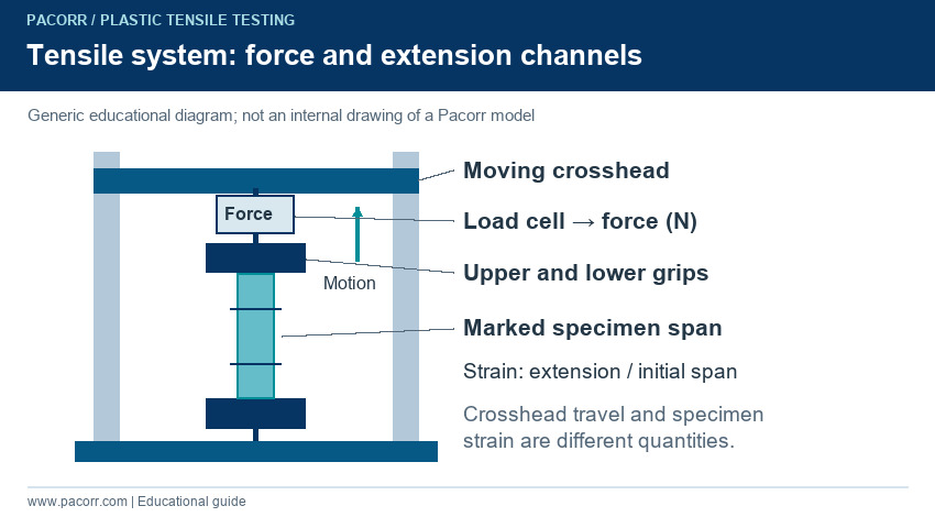
A drive moves the crosshead, the grips transmit an axial pulling force, and a load cell measures that force. A displacement or strain-measurement system tracks the selected extension quantity. The controller records signals against time; calculations combine those signals with the specimen dimensions and reference length.
These are related but distinct functions. A force sensor does not directly measure stress, and a movement encoder does not automatically measure strain between specimen marks. The generic diagram separates the force path from the measurement channels. Buyers should ask which channels are present in the quoted system and which properties its software calculates from each one. A graph labelled stress–strain is meaningful only when both axes have a defensible measurement basis.
How should load-cell capacity and usable range be selected?
Estimate force from expected stress multiplied by the original area, then allow for uncertainty in the material and the intended tests. A thin strip may need only a small fraction of the force required by a moulded coupon. For illustration, 40 MPa acting on 0.75 mm² corresponds to 30 N; 60 MPa acting on 40 mm² corresponds to 2,400 N. These are planning examples, not material specifications.
Choose a calibrated measurement range that covers the expected forces with adequate performance. A large frame's maximum capacity does not prove that very small forces are measured well. Ask for the usable verified range, relevant uncertainty, overload limits and any interchangeable load-cell arrangements. Compare those details with the lowest meaningful force as well as the maximum expected load.
What makes a suitable grip and alignment arrangement?
The grip must hold the specimen securely while avoiding premature damage. Thin films may need a different face material or clamping arrangement from thick moulded coupons. Excessive pressure can damage the material, while insufficient pressure can permit movement that looks like elongation. No single jaw-face pattern or pressure is correct for every plastic.
Mount the specimen centrally, with its tensile axis aligned through the grip system. Keep film flat and avoid twisting. Watch for movement at the jaws and retain the failure location. During development, use representative samples to establish a repeatable clamping instruction, then control it in routine testing. If a setup needs changing, document the change and evaluate its effect before merging the new results with an earlier production trend.
Are gauge length, grip separation and crosshead travel the same?
No. Gauge length identifies the initial span used to calculate a particular strain measurement. Grip separation describes the distance between gripping boundaries. Crosshead travel is movement of a machine component. Depending on the arrangement, machine and fixture deformation, seating and slip can contribute to the travel signal.
Define the reference length and extension channel in the test record. A displayed extension of 10 mm has different percentage meanings when divided by 25 mm or 50 mm. Neither reference length should be selected simply because it makes the result resemble a supplier's certificate. When the procedure permits more than one extension method, retain the chosen method consistently and disclose it when sharing results between laboratories.
When is an extensometer important?
An extensometer measures extension over an identified specimen span. Contact and non-contact arrangements have different practical constraints: contact force and attachment can affect delicate samples, while optical approaches require suitable visibility, tracking and validation. The appropriate choice depends on the property, expected extension and specimen behaviour.
Small-strain measurements deserve particular care. A system suitable for a large breaking extension may not resolve the small changes needed for modulus. ASTM E83 covers calibration, verification and classification of extensometer systems. Check performance over the actual gauge length and strain range used. Do not equate display resolution with accuracy, and do not assume that a force-calibration certificate verifies the strain channel as well.
How should test speed and strain rate be chosen?
Take the required speed, reference length and any property-specific stages from the controlled method. A speed copied from a previous job is not a universal setting for films or moulded plastics. The expected extension behaviour and the property being measured matter when configuring the test.
Crosshead speed is normally expressed in mm/min; strain rate expresses change in strain per unit time. Under a simplified uniform-extension assumption, nominal strain rate is speed divided by initial length. For an illustrative 50 mm reference length, 50 mm/min gives 1 min⁻¹, whereas 5 mm/min gives 0.1 min⁻¹. Actual specimen strain rate can differ. These examples explain the relationship and are not prescribed D638 or D882 settings. If the selected machine cannot provide the required speed, choose a suitable configuration rather than substituting the nearest available setting.
What is an educational D638 testing workflow?
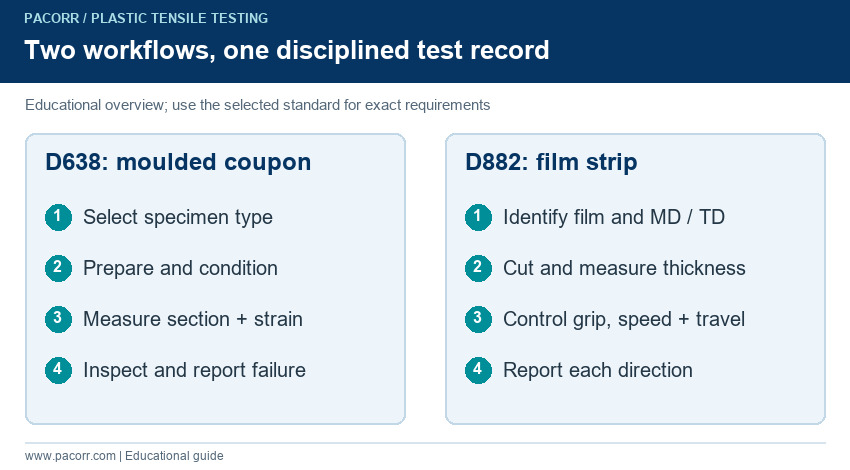
Use the following sequence to plan a controlled laboratory instruction. The applicable standard supplies the detailed specimen, measurement and operating requirements.
- Define the material, purpose, required property, edition and applicable material specification.
- Select the specimen type and preparation route; identify orientation and source location.
- Condition and inspect the specimens, then measure the required original dimensions.
- Confirm force range, grips, alignment, speed capability and strain-measurement suitability.
- Mount the coupon without bending or unintended loading, and establish the required reference length.
- Apply the specified loading sequence while recording the relevant force and extension channels.
- Record the failure location and any slip, abnormal deformation or interruption.
- Apply the method's validity rules, calculations and reporting requirements to the complete set.
Keep raw records and the method configuration together. Pacorr's related guide to tensile testing rigid plastics provides additional application context; use the controlled standard for exact operating requirements.
What is an educational D882 testing workflow?
Film testing needs its own setup review, especially for cutting, gripping and large extension. Do not simply reuse a moulded-coupon program with a different sample name.
- Identify the film construction, nominal thickness, roll position, direction and requested property.
- Select the required strip geometry, sampling plan, conditioning and extension method.
- Cut clean, parallel specimens and preserve their MD or TD identity.
- Measure the required dimensions without damaging or unintentionally compressing the film.
- Check force sensitivity, grip faces, initial separation, speed and available travel.
- Mount the strip flat and centrally, following the defined seating and zeroing sequence.
- Run the prescribed test, recording the signals and observing slip, tearing and the break location.
- Assess validity, calculate the specified outputs and report each direction separately.
A highly extensible strip can exceed available travel before breaking. Report a reached travel limit as a test limitation, not as elongation at break. Reconfigure the test only through an approved procedure.
How should a plastic stress–strain curve be interpreted?
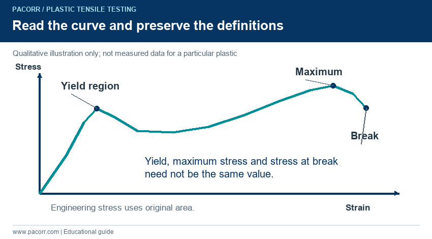
The initial portion describes how stress develops with strain. Some plastics show a recognisable yield event, followed by necking or drawing; others fail without a clear yield point. Later strain hardening can create a maximum stress after the first yield. Consequently, yield stress, maximum tensile stress and stress at break are not automatically the same number.
| Reported quantity | Meaning to preserve |
|---|---|
| Maximum force | Highest measured pulling force, in N. |
| Engineering tensile stress | Force divided by original section area, commonly MPa. |
| Elongation or strain at break | Extension at rupture relative to its defined original length. |
| Tensile modulus | A prescribed measure of stress–strain slope. |
Review the curve alongside observations. A sudden change may represent material behaviour, grip slip or a measurement interruption. The explanatory illustration is qualitative; its shape is not a reference curve for a particular polymer grade.
How do you calculate tensile stress with correct units?
For a rectangular specimen, original area A₀ = width × thickness. Engineering stress σ = force / A₀. When force is in newtons and dimensions are in millimetres, N/mm² equals MPa. Convert micrometres to millimetres before calculating: 50 micrometres is 0.050 mm.
Consider an illustrative film strip 15.0 mm wide and 0.050 mm thick. Its area is 0.750 mm². A measured maximum force of 30.0 N gives 40.0 MPa. A separate moulded coupon with a measured section of 10.0 × 4.0 mm and a maximum force of 2,400 N gives 60.0 MPa. These dimensions and forces are arithmetic examples, not prescribed specimen dimensions or acceptance targets.
Do not confuse kg with force. Where an instrument reports kgf, convert consistently: 1 kgf equals 9.80665 N. Preserve the original reading and conversion in the data record rather than changing units midway through a spreadsheet.
How is elongation calculated, and why does the reference matter?
Engineering strain is extension divided by the defined original reference length. Multiply the ratio by 100 to express it as a percentage. If a valid measurement over an initial 50 mm span records 75 mm of extension, the engineering strain is 1.5, or 150%; the final length of that span is 125 mm.
This example assumes that the extension signal actually represents the stated span. Dividing total crosshead movement by an unrelated gauge length does not establish specimen strain. Keep the software's channel selection, reference-length entry and any transition between measurement systems visible in the method record. If an extensometer is removed before rupture, do not silently present its last recorded value as elongation at break or splice another channel without an approved calculation approach.
How do modulus, strength and energy absorption differ?
Strength relates to stress at a specified event. Modulus describes a slope, so it is especially sensitive to strain measurement, seating and the selected calculation interval. A tangent, chord or secant construction is not interchangeable without explanation. Use the definition and interval required by the method; do not apply an arbitrary line between two convenient points.
The area under a valid engineering stress–strain curve represents work per original volume under the relevant assumptions. If strain is stored as percent, convert it to a fraction before integration. An illustrative integral of 5 MPa over dimensionless strain corresponds to 5 MJ/m³. This dimensional example does not prescribe an integration algorithm. Strength and energy absorption can rank materials differently, so request the property that addresses the real application instead of assuming the highest peak is always preferable.
Which failure patterns require investigation?
Inspect the broken specimen before discarding it. A break at a jaw, visible sliding, edge-driven tearing, an over-range signal or loss of strain tracking requires evaluation under the chosen method's validity rules. A low number alone is not a valid reason to reject a result.
| Observation | Practical investigation |
|---|---|
| Repeated failure close to a jaw | Check jaw condition, pressure, alignment and preparation. |
| Large extension with little specimen stretching | Check slip, seating and the selected displacement channel. |
| One direction differs from another | Confirm MD/TD labels, sampling positions and process orientation. |
| Unexpected stress shift across a batch | Check actual thickness, units, force range and method revision. |
Keep the original result, observation and exclusion reason traceable. Repeated retesting until a passing result appears conceals a process or measurement problem. Treat the investigation as part of quality control rather than an inconvenience to be removed from the dataset.
How should sampling, scatter and acceptance limits be handled?
Use the number of specimens and acceptance procedure required by the selected method and specification. Distinguish specimens from repeated calculations of the same test. Separate orientation groups, preparation batches and any agreed material states. A mean from a small, selectively chosen area should not be represented as the performance of an entire production roll.
Report the requested summary together with useful dispersion information and valid specimen count. Establish whether the limit applies to individual results, a mean, a minimum or another defined statistic. Agree the treatment of measurement uncertainty and borderline outcomes before testing. No universal pass/fail strength exists for all plastic films or moulded plastics; a method tells you how to measure, while an approved product specification tells you what performance is required.
Can D638 and D882 results be converted or compared directly?
There is no universal conversion factor between the two methods. Even when a polymer name is the same, film processing and moulding can produce different structure and orientation. Matching units does not make the underlying experiments equivalent. Compare like-for-like specimens and procedures whenever a supplier decision depends on a numerical difference.
When two laboratories disagree, exchange the full test configuration before concluding that one machine is wrong. Check specimen source, dimensions, direction, conditioning, speed, extension channel, reference length, data reduction and exclusions. Pacorr's tensile-strength formula and interpretation guide explains why a force value and a material stress value answer different questions. A coordinated comparison with traceable samples is more informative than comparing isolated certificate averages.
What changes for multilayer, printed and coated films?
For a whole-construction test, retain the full layer stack and describe what was actually tested. Do not divide the total force by one selected layer's area and label the result as that layer's tensile strength. Load sharing and interfacial behaviour make that interpretation unsupported without a separate validated analysis.
Record printing, coatings, adhesive cure state and any relevant ageing history. A tear, delamination or local defect may change the observed failure mechanism. If the real question concerns bond strength between layers, choose an appropriate peel or adhesion method instead of expecting an intact-strip tensile result to isolate the interface. Explain whether a reported result characterises the finished construction, a constituent film or a deliberately prepared comparison sample.
What matters for moulded, recycled and reinforced plastics?
Record the grade and relevant processing history rather than using only a broad name such as polypropylene. Recycled content, filler distribution, moisture, thermal history and moulding conditions are useful investigation variables, but a tensile result alone cannot identify which one caused a change. Use controlled comparisons and complementary measurements when diagnosing a process problem.
For reinforced materials, confirm the correct standard for the reinforcement architecture. Continuous-fibre laminates and particular oriented high-modulus fibre systems may require a composite-specific route; the ASTM D3039/D3039M scope is relevant to polymer-matrix composite tensile testing. Avoid extending a result from a conveniently cut coupon to a complex part without considering direction, structural features and service loading.
How do ISO methods, seal tests and service tests fit in?
The ISO 527-3 film-and-sheet method addresses a related subject, while the ISO 527 family also includes general principles and moulding-material conditions. Similar subject matter does not make ASTM and ISO procedures automatically interchangeable. Identify the required standard on the order and report rather than writing an unsupported combined compliance claim.
A seal-strength question belongs to an appropriate method such as ASTM F88/F88M, not to a base-film strength calculation. Tear, puncture, impact and long-duration loading require their own assessments. NPL's guide to measurement and analysis of creep in plastics illustrates why time-dependent behaviour needs separate data. A short tensile test should not be turned into an unsupported lifetime or package-load claim.
Which Pacorr machine details must be checked before ordering?
The official Pacorr Tensile Testing Machine page lists model PCTTM-1, selectable capacities from 50 to 5,000 kgf, a 40–400 mm/min speed range, 700 mm vertical clearance, 0.1 mm elongation display increment and vice-type jaws as the default arrangement. These are listing values, not proof that every configuration performs every D638 or D882 procedure.
The practical checks are specific. Confirm whether the required speed lies within the offered range, whether the expected low force is inside the verified measurement range, and whether the strain system can support the requested property. A 0.1 mm display step does not establish modulus capability. Vertical clearance is not automatically usable specimen extension after grips and fixtures are installed. Ask Pacorr to confirm the exact configuration against your controlled method and representative specimens.
What calibration and verification evidence should be requested?
Force, extension and speed are different measurement functions. ASTM E4 addresses force calibration and verification of testing machines; it is not a complete purchase specification and does not by itself verify every output in a tensile report. Review the certificate's actual range, measurement direction and associated uncertainty.
Maintain checks for the dimension-measuring instruments and strain system as applicable. Reassess performance after repairs, overloads, relocation or an unexplained shift. Set intervals through the quality system, usage and stability history rather than assuming that every instrument needs the same interval. A current certificate is most useful when it can be connected to the configuration used for the test, including the installed load cell and any relevant accessories.
What should a quotation include, and what affects price?
A current fixed selling price was not verified, so request a configuration-specific quotation. Cost depends on load cells, controller and data software, speed capability, travel, grips, extensometry, specimen preparation and calibration documentation. Confirm delivery, installation, training and service scope separately where needed.
Send the supplier a short application sheet: material construction, thickness and width range, expected force and extension, required properties, standard edition, specimen type, laboratory environment and data needs. Request a demonstration with representative difficult specimens as well as ordinary ones. For a laboratory testing both films and moulded coupons, ask how changeover is controlled and which accessories are shared. The right purchase is a documented measurement system suited to the work, not simply the largest machine capacity.
What should the final tensile-test report contain?
Include specimen identity and source, direction, preparation, dimensions, conditioning, test environment, standard edition and deviations. Identify the machine, load cell, grip arrangement, speed, reference length and extension channel. State the requested property definitions and units; retain the raw curve or traceable data file, valid count, individual results where required, summary statistics and failure observations.
For a conformity statement, identify the product limits and decision rule. Where a limitation prevented a requested output, state it directly. For example, travel-limited extension is not a measured breaking extension. A report should let a technically competent reviewer understand what was measured, how it was calculated and which product decision it can support without reconstructing undocumented settings from memory.
Frequently asked questions
Is a flexible sheet automatically a D882 specimen?
No. Flexibility alone is insufficient. Check thickness, specimen form and the governing material or customer specification before selecting the method.
Can several film layers be stacked to use D638?
Stacking changes the specimen into an assembly with interfaces and different gripping behaviour. Do not use it as an automatic substitute for testing the original film.
Is there one correct test speed for all plastics?
No. Use the speed and any property-specific sequence required by the controlled method and material specification. Confirm that the machine can provide them.
Are maximum force and tensile strength the same?
No. Maximum force is a load reading. Engineering tensile strength uses the relevant force divided by the original cross-sectional area, with consistent units.
Can crosshead movement always replace an extensometer?
No. Crosshead movement can include effects outside the intended specimen span. Use the extension method permitted for the requested property and record its reference length.
Should MD and TD results be averaged together?
Keep the directions separate unless an approved specification explicitly defines another reporting approach. Mixing them can hide directional behaviour.
Does a high-capacity machine necessarily suit thin films?
No. Check the verified low-force range, grips, extension measurement and travel. Maximum frame capacity alone does not establish suitable film-test performance.
Does a load calibration certificate verify modulus?
Not by itself. Modulus also depends on strain measurement, dimensions, setup and the prescribed calculation. Review the complete measurement system.
Can one tensile result establish pouch seal strength?
An intact-film tensile result does not isolate a seal. Select an appropriate seal-strength method and specimen arrangement for that question.
Are the worked dimensions and loads mandatory settings?
No. They are illustrative arithmetic and planning examples. Obtain specimen dimensions, tolerances and operating settings from the controlled method.
Is there a universal conversion from D638 to D882 results?
No. Method, specimen form, processing and orientation affect the comparison. Use matched testing rather than an assumed conversion factor.
What should I send Pacorr for machine selection?
Send the material, thickness, specimen geometry, standard edition, required properties, expected force and extension, and reporting requirements so that the configuration can be assessed.
Discuss your plastic tensile-testing requirement with Pacorr
For a laboratory comparing films and moulded plastics, start with the specimen and the required measurement. Share your application with Pacorr and request confirmation of the load range, grips, speeds, usable travel and strain-measurement arrangement for the proposed system.
Review the Tensile Testing Machine and contact Pacorr Testing Instruments at +91-8882149230 or info@pacorr.com. A documented application review helps turn a standard number into a practical, traceable testing setup.