
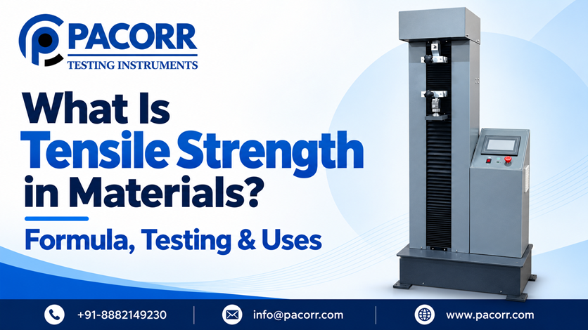
Tensile strength is the maximum engineering stress a material sustains during a tensile test. It is calculated by dividing the highest recorded pulling force by the specimen’s original cross-sectional area. Usually expressed in megapascals (MPa), tensile strength helps compare materials and check whether production meets a specified requirement.
A packaging film, a rubber strip and a steel rod can all carry a pulling load, but they respond differently. One may stretch considerably, another may deform permanently, and another may fracture with little visible extension. Measuring the force alone does not explain those differences.
This guide explains tensile strength, its formula and units, how to calculate it, and how to interpret a tensile test for material selection and quality control.
In this guide
- Tensile strength meaning and related terms
- Formula, symbols and units
- Worked tensile strength calculations
- Testing procedure and standards
- Yield strength, tensile strength and breaking strength
- Material differences and industrial uses
- Factors affecting results and common mistakes
- Frequently asked questions
- Conclusion
What does tensile strength mean?
“Tensile” describes tension: a force that pulls or stretches an object. Tensile strength describes the highest tensile stress reached under the conditions of a test. It is often called ultimate tensile strength, or UTS.
The distinction between force and stress matters. A thick specimen can carry more force than a thin specimen made from the same material. Dividing force by cross-sectional area makes their results more useful for comparing material strength.
Three terms help keep a test report clear:
| Term | Meaning | Typical unit |
|---|---|---|
| Tensile force or tensile load | The pulling force applied to the specimen | N or kN |
| Tensile stress | Applied force divided by the relevant cross-sectional area; engineering stress uses the original area | MPa or N/mm² |
| Ultimate tensile strength | The maximum engineering stress recorded during the test | MPa or N/mm² |
Tensile strength is not automatically the stress at the instant of fracture. A ductile specimen can reach its maximum load, continue deforming and then break at a lower load. A report should distinguish the peak result from the result at break.
What is the tensile strength formula?
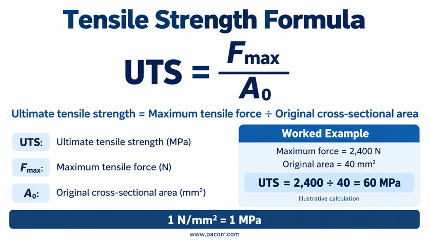
The formula for ultimate tensile strength is:
UTS = Fmax / A₀
Where:
- UTS is ultimate tensile strength.
- Fmax is the maximum tensile force recorded during the test.
- A₀ is the specimen’s original cross-sectional area in the test section.
You may also see tensile strength represented by σu or Rm. Symbols vary between standards and reports, so define the notation whenever you present a calculation.
For tensile stress at any particular point in the test, use the force at that point:
Engineering tensile stress, σ = F / A₀
The difference is the force selected. The general stress equation uses the current load; the ultimate tensile strength equation uses the maximum load.
How do you calculate cross-sectional area?
Use the original dimensions of the section specified by the test method.
| Specimen section | Original area formula | Dimensions needed |
|---|---|---|
| Rectangular strip | A₀ = width × thickness | Width and thickness |
| Solid circular rod | A₀ = πd² / 4 | Original diameter, d |
| Circular hollow tube | A₀ = π(D² − d²) / 4 | Outside diameter, D, and inside diameter, d |
For a reduced-section specimen, measure the test section rather than the wider grip ends. Threaded fasteners require particular care: use the tensile stress area and procedure specified for the fastener instead of treating the nominal thread diameter as a plain rod diameter.
What are the units of tensile strength?
Tensile strength has units of stress: force divided by area.
| Unit | Meaning | Conversion |
|---|---|---|
| Pa | Pascal | 1 Pa = 1 N/m² |
| MPa | Megapascal | 1 MPa = 1,000,000 Pa |
| N/mm² | Newton per square millimetre | 1 N/mm² = 1 MPa |
| psi | Pound-force per square inch | 1 MPa ≈ 145.038 psi |
| ksi | Thousand pounds-force per square inch | 1 ksi = 1,000 psi ≈ 6.895 MPa |
Keep the units consistent before dividing. If force is in newtons and area is in square millimetres, the answer is directly in N/mm², equivalent to MPa. If force is in kilonewtons, multiply it by 1,000 first.
How to calculate tensile strength: worked examples
To calculate tensile strength, measure the original test-section area, identify the maximum load, convert both inputs to compatible units and divide the load by the area.
The examples below use illustrative values to explain the calculations. They are not Pacorr laboratory results or specifications for a particular material grade.
Example 1: A rectangular plastic specimen
Suppose the original test section is 10 mm wide and 4 mm thick. The maximum recorded force is 2,400 N.
- Original area: 10 × 4 = 40 mm².
- Maximum load: 2,400 N.
- Tensile strength: 2,400 ÷ 40 = 60 N/mm² = 60 MPa.
If the load at fracture is 2,000 N, the engineering stress at break is 2,000 ÷ 40 = 50 MPa. The UTS remains 60 MPa because that was the highest engineering stress reached.
Example 2: A round metal specimen
Suppose a solid specimen has an original diameter of 8 mm and reaches a maximum load of 25 kN.
- Original area: π × 8² ÷ 4 ≈ 50.27 mm².
- Convert the force: 25 kN = 25,000 N.
- Tensile strength: 25,000 ÷ 50.27 ≈ 497.4 MPa.
Using the diameter itself as the area would produce an incorrect result. The area calculation must come first.
Example 3: A thin packaging film
Suppose a film strip is 15 mm wide and 0.05 mm thick, with a peak load of 30 N.
- Original area: 15 × 0.05 = 0.75 mm².
- Tensile strength: 30 ÷ 0.75 = 40 MPa.
Thickness measurement becomes especially important for thin films. If 0.04 mm were entered incorrectly, the calculated result would be 30 ÷ 0.60 = 50 MPa: a 25% overstatement caused by the area input alone.
Can you calculate the tensile load from tensile strength?
Rearranging the equation gives:
Estimated peak tensile load = UTS × original area
For an illustrative UTS of 50 MPa and an area of 20 mm², the corresponding peak load is 50 × 20 = 1,000 N.
This is a useful first estimate for planning a test. It is not a safe working-load rating. Product design also needs the applicable design rules, material variability, loading conditions and relevant failure limits.
How is tensile strength measured?
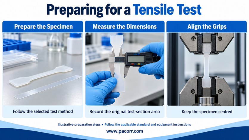
A tensile testing machine holds a specimen between grips and pulls it under controlled conditions. A load cell measures force. The resulting measurements, together with the specimen dimensions, allow the operator or software to calculate tensile properties.
For an equipment introduction, read Pacorr’s guide to what a tensile testing machine is and how it works.
1. Choose the material-specific test method
Start with the material, product specification and purpose of the test. These determine the appropriate specimen geometry, conditioning, speed, measurement method and reporting requirements.
A tensile test for a moulded plastic coupon is not interchangeable with a test for a thin film, rubber strip or metal specimen.
2. Prepare and condition the specimens
Prepare the prescribed shape with clean edges and without unintended damage. Specimens are not universally dumbbell-shaped: the correct form depends on the material and method.
Record the batch and sampling direction. Apply the required temperature, humidity and conditioning procedure before testing.
3. Measure the original dimensions
Measure width, thickness or diameter where the method specifies. Record the original gauge length when strain or elongation is required. Enter the measured dimensions for each specimen rather than assuming every specimen has the same area.
4. Set up the load cell, grips and strain measurement
Choose a force range suitable for the expected load. Align the specimen with the pulling axis, and use grips that prevent slipping without creating premature damage.
When the method requires accurate specimen strain, use the appropriate extensometer or permitted measurement system. Crosshead travel can include grip movement and machine deformation, so it is not automatically identical to specimen extension.
5. Run the prescribed test
Apply the specified speed or control method and record the load response through the required endpoint. Avoid using one convenient speed for every material; the test conditions are part of the result.
6. Check the failure and report the results
Review the force curve and failure location. Apply the standard’s validity rules to grip failures, slipping or other unusual behaviour. Test the required number of specimens and retain individual results alongside any averages and variability measures.
Pacorr’s guide to using a tensile testing machine for material strength analysis provides additional setup context. Always use the applicable standard and the machine’s operating instructions for the actual procedure.
Which standards are used for tensile testing?
The appropriate standard depends on what is being tested and which properties are required.
| Material or specimen | Common standard families | Important distinction |
|---|---|---|
| Moulded and extruded plastics | ASTM D638; relevant parts of ISO 527 | Check specimen type, conditioning and test settings |
| Thin plastic sheeting and films | ASTM D882; ISO 527-3 | Film direction, dimensions and extension measurement matter |
| Metallic materials | ASTM E8/E8M; ISO 6892-1 | Use the specified geometry and test-control requirements |
| Vulcanized and thermoplastic rubber | ASTM D412; ISO 37 | Large extension and the defined reporting properties require attention |
These are examples, not declarations that the methods are equivalent. ASTM D638 and ISO 527-2, for example, differ in procedural requirements. Select the edition required by the customer or specification and confirm its applicability.
The ASTM D882 scope covers thin plastic sheeting and films below 1.0 mm thickness. ISO 37 addresses tensile stress–strain properties of vulcanized and thermoplastic rubbers. A standard’s public scope helps identify the right document; it does not replace the complete procedure.
Yield strength vs tensile strength vs breaking strength
These measurements answer different questions and should not be used interchangeably.
| Property | What it describes | Why it matters |
|---|---|---|
| Yield strength | The stress associated with yielding, or a specified proof/offset criterion | Helps assess permanent deformation |
| Ultimate tensile strength | The highest engineering stress reached | Describes peak tensile resistance under the test conditions |
| Engineering stress at break | Force at fracture divided by original area | Describes the final fracture point |
| Elongation at break | Extension at break relative to original gauge length, as defined by the method | Describes how far the specimen extends before breaking |
| Tensile modulus | The defined stress–strain slope used to describe stiffness | Describes resistance to elastic stretching |
“Breaking strength” can be used for a force or a stress, depending on the product and test method. Check the definition and units before comparing two reports.
A high UTS does not automatically mean high stiffness, high ductility or good resistance to repeated loading. A material may resist a large peak stress yet extend very little before fracture.
Pacorr’s stress–strain curve guide explains how the curve connects stiffness, yielding, maximum stress and fracture.
Why does tensile strength differ between materials?
There is no single tensile strength value for “plastic,” “steel” or “rubber.” A useful value belongs to an identified grade, condition, direction and test method.
| Material group | Information to record before comparing results |
|---|---|
| Steel and reinforcement steel | Grade, specification, processing condition and applicable test method |
| Aluminium alloys | Alloy designation, temper and specimen orientation |
| Plastics | Polymer grade, fillers, processing history and conditioning |
| Rubber | Compound, curing condition, ageing and test conditions |
| Films and laminates | Layer structure, thickness and machine/transverse direction |
| Fibre composites | Fibre type, orientation, lay-up and specimen preparation |
For reinforcement steel, do not substitute a grade’s yield requirement for its tensile strength. Read the specified properties separately and use a traceable test certificate or the applicable material specification.
Similarly, a steel designation alone does not establish a universal UTS for every heat-treatment condition. A material table without those details can look precise while giving the reader an unsuitable comparison.
What is specific tensile strength?
Specific tensile strength is tensile strength divided by density:
Specific tensile strength = UTS / density
It helps compare strength relative to weight. In SI units, Pa divided by kg/m³ gives N·m/kg, equivalent to m²/s².
For illustration, Material A with a UTS of 300 MPa and density of 3,000 kg/m³ has a specific tensile strength of 100,000 N·m/kg. Material B with 500 MPa and 7,500 kg/m³ gives approximately 66,667 N·m/kg. B has the higher UTS; A has the higher strength relative to density. Other design requirements still need separate evaluation.
What is tensile strength used for?

Selecting materials for a product
Tensile data helps narrow the choice of materials for a required loading condition. Compare it with stiffness, elongation, operating temperature, environmental resistance and cost before making a final selection.
Checking incoming materials and supplier consistency
Comparable tests can help identify differences between deliveries. Keep the method and conditioning consistent so that a change in the result is not simply a change in the test setup.
Pacorr’s article on tensile strength evaluation for global suppliers discusses its role in supplier quality evaluation.
Evaluating films and flexible packaging
Tensile testing helps assess how a film responds to stretching during handling and processing. Test the relevant directions separately where required. Combine tensile information with other application-specific tests: a film’s tensile result alone does not establish the performance of a finished pouch seal.
Comparing production changes
When a material formulation or manufacturing setting changes, compare specimens using a consistent test plan. Review the curve and failure behaviour as well as the maximum number; two batches can have similar UTS values but different extension at break.
Investigating failures
A tensile test can contribute evidence when a product stretches excessively or breaks unexpectedly. Compare affected and reference samples, record the sampling locations and investigate the service conditions. The test should support the investigation rather than replace it.
What factors affect tensile strength results?
Separate actual changes in the material from errors introduced during measurement.
Material-related factors include composition, processing history, orientation, defects, ageing and environmental exposure. Their effects depend on the material; a treatment that improves one property can reduce another.
Test-related factors include specimen dimensions, conditioning, alignment, test speed, gripping, force measurement and the method used to measure extension.
A useful troubleshooting sequence is:
- Confirm the material and batch identity.
- Check the test method and conditioning records.
- Recheck original dimensions and software inputs.
- Inspect the grips, alignment and failure location.
- Compare the complete curves and repeat results under the required procedure.
This sequence helps avoid changing a production process to correct what was actually a measurement problem.
Common calculation and reporting mistakes
| Mistake | Why it matters | Better practice |
|---|---|---|
| Reporting peak force as tensile strength | N is a force unit, not a stress unit | Divide by original area and report the stress unit |
| Mixing kN and N | Can introduce a factor-of-1,000 error | Convert force before calculating |
| Using the final necked area for engineering UTS | Changes the definition of the result | Use original area for engineering UTS |
| Substituting break load for peak load | Can understate UTS | Identify maximum force from the recorded data |
| Comparing different specimen directions | Can hide directional behaviour | Report orientation and compare like with like |
| Reporting only an average | Can conceal wide variation | Retain individual results and relevant variation measures |
How do you choose a tensile testing machine?
Begin with a test requirement, not only a maximum machine capacity. Provide the supplier with the material, specimen dimensions, expected force, required standard and measurements needed.
Check the suitability of the force-measurement range, grips, available travel, speed/control options and strain-measurement arrangement. Confirm which results the proposed configuration can determine and what supporting calibration or verification is needed.
For equipment options, explore the Pacorr Tensile Testing Machine. Discuss the actual sample and test method with the Pacorr team so the machine configuration matches the intended application.
Frequently asked questions
What is tensile strength in simple words?
Tensile strength describes the greatest pulling stress a material reaches during a tensile test. It accounts for specimen area, which makes it more useful for comparing materials than pulling force alone.
How do I find tensile strength from a test report?
Find the maximum force and original test-section area, then divide force by area using compatible units. If the report already lists UTS or Rm, check its units and confirm that it refers to maximum stress rather than stress at break.
Is MPa the same as N/mm²?
Yes. One MPa equals one N/mm². A calculated result of 45 N/mm² can be reported as 45 MPa without changing its numerical value.
What does high tensile strength mean?
It means the material sustains a relatively high maximum tensile stress compared with an appropriate reference. There is no universal threshold that makes every material “high tensile.” The grade, application and comparison group matter.
Can I use a tensile strength calculator instead of testing?
A calculator can divide a known peak force by a known original area. It cannot establish the peak force for an unknown specimen. To determine actual strength, use suitable testing or verified data applicable to the exact material and condition.
Is tensile strength the same as tensile stress?
No. Tensile stress can be calculated at any point during loading. Ultimate tensile strength is the maximum engineering tensile stress reached in the test.
Is the strength coefficient the same as ultimate tensile strength?
No. A strength coefficient is a parameter in certain material stress–strain models. UTS is the maximum engineering stress measured in a tensile test. Check the model definition before using its parameters in a calculation.
Can tensile strength vary within one product?
Yes. Different locations or directions may have different material structures or processing histories. Sampling should reflect the product and the applicable specification; a result from one small specimen does not automatically represent every location.
Does a higher tensile strength always mean a better material?
No. The best choice depends on the application. A component may also need controlled stiffness, sufficient ductility, resistance to repeated loading, low weight or performance at a particular temperature.
Conclusion
Tensile strength connects a material’s maximum pulling force with the area carrying that force. The calculation is straightforward: divide maximum tensile load by original cross-sectional area. Obtaining a meaningful result requires the right specimen, reliable dimensions, controlled testing and a clearly defined reporting method.
Use tensile strength alongside yield behaviour, elongation and stiffness, and compare results obtained under compatible conditions. This makes the data more useful for choosing materials, checking suppliers and investigating production changes.
If you are planning tensile testing for your materials, share your sample details, expected load and required standard with Pacorr. A suitable testing configuration helps turn a strength value into information your quality team can use.
Recent Blogs
Enhance your understanding of testing and precise quality control indistinct applications with our
knowledge based articles coming from top editors of industry leaders.

Our USP's
Demonstration of Machine
- Try Before You Decide
- Experience Before You Invest
- See It in Action – Free Demo
Global Reach
- Delivering Excellence Worldwide
- Serving Across Borders
- Your Global Supply Partner
On-Site Support
- Support That Comes to You
- On-Ground Assistance, Anywhere
- We Reach Where You Are
Team Strength
- Powered by Expert Minds
- Driven by Skilled Professionals
- Engineering Excellence Team
Manufacturing
- Precision-Driven Manufacturing
- Smart & Automated Production
- Engineered In-House Excellence
