
Static COF (μs) = the valid force at the start of sliding ÷ normal force. Kinetic COF (μk) = the mean force over the prescribed sliding interval ÷ normal force. A coefficient of friction tester records the force trace needed for these calculations. Use the same force unit in the numerator and denominator, such as newtons. The coefficient has no unit.
For an illustrative horizontal sled with a total loaded mass of 0.200 kg, the normal force is approximately 1.96133 N at standard gravity. A valid starting peak of 0.600 N gives μs ≈ 0.306. An average sliding force of 0.400 N gives μk ≈ 0.204. These are calculation examples. A real result belongs to the tested pair of surfaces and the selected method, direction and conditions.
What does a coefficient of friction tester measure?
In a horizontal film test, one surface is attached to the underside of a sled and the opposing surface is held flat on a test plane. The instrument measures the force as one surface moves relative to the other. The force needed at the onset of sliding and the force while the surfaces are already sliding describe different stages of the same contact.
Film can be tested against another film or against a specified counterface, such as a suitable metal surface. Define the contact pair before testing. The inside face of a printed laminate against its outside face can behave differently from outside against outside. Film against stainless steel answers another question again. A certificate that gives only “COF 0.25” leaves the reader unable to tell which surfaces were tested or whether the value is static or kinetic.
ASTM D1894-24 permits a moving sled on a stationary plane or a stationary sled held by the measuring system over a moving plane. Either arrangement needs the prescribed line of force, specimen mounting and data capture. The principle is relative motion at the interface. The mechanics and schematic examples below use a moving sled to make the force directions easier to see.
How do you determine the normal force on a horizontal sled?
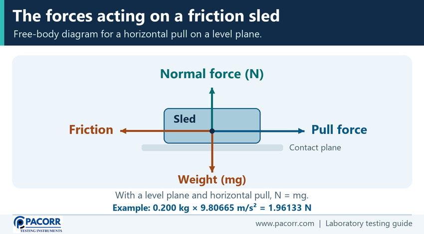
The normal force is the contact force perpendicular to the test plane. The sled has weight acting downwards and the plane pushes back upwards. With a level plane, horizontal line of pull, no other vertical loads and no vertical acceleration, the magnitude of the normal force equals the loaded sled weight.
Normal force (N) = loaded mass (kg) × gravitational acceleration (m/s²) under those conditions. In the worked example, 0.200 × 9.80665 gives 1.96133 N. The number 9.80665 is the conventional value for standard gravity. Keep the unrounded intermediate result through the calculation, then report the coefficient at the precision required by the procedure.
Check the method's definition of sled mass and the required assembly before calculating. The normal load comes from the supported assembly, so the lab should account for any attachments or mounted materials as required. The load cell's maximum rating is a force capacity and does not establish the normal load. Likewise, the specimen's area may affect contact conditions, but you do not divide the measured force by that area to obtain COF.
How do you calculate static COF from the starting peak?
Static friction resists motion while the surfaces remain at rest relative to each other. As the horizontal pull increases, the resisting force can increase until relative sliding starts. Select the valid onset event using the method. For a trace with a clear starting peak, use the force at that event for the numerator.
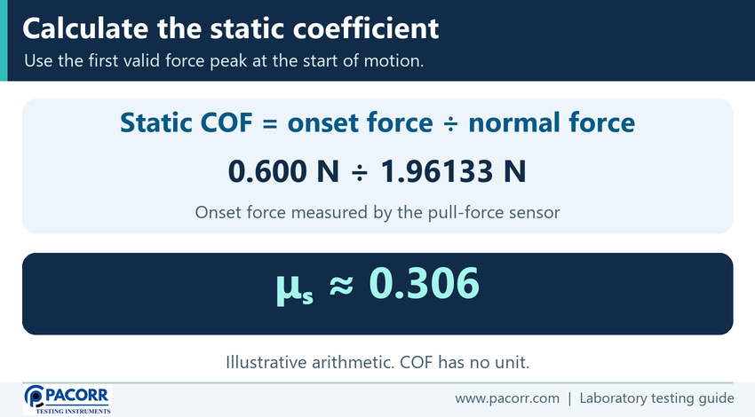
μs = Fₛ ÷ normal force, where Fₛ is the valid starting force. With a 0.600 N starting peak and a normal force of 1.96133 N, the arithmetic is 0.600 ÷ 1.96133 = 0.30591486…, reported here as 0.306.
The first local spike on a graph can come from slack, a fixture impact, electrical noise or an abrupt change in loading. Likewise, a taller feature late in the run can occur after sliding has started. Neither automatically qualifies as the static event. Confirm the onset of relative motion and review the trace against the method before reporting a static value. A peak hold function is useful only if it captures the relevant event.
For the underlying force balance before the threshold and a separate starting-force example, see Pacorr's explanation of the static friction coefficient.
How do you calculate kinetic COF from the sliding force?
Kinetic COF describes the resistance during sliding. The pulling force can vary while the sled travels across the test surface. Use the average force over the method's specified measurement interval, starting and ending at the prescribed points. Check how the software determines those boundaries, such as by time or displacement.
μk = Fₖ,mean ÷ normal force, where Fₖ,mean is the mean force over the approved interval. With a mean sliding force of 0.400 N, the arithmetic is 0.400 ÷ 1.96133 = 0.20394324…, or 0.204 in this example.
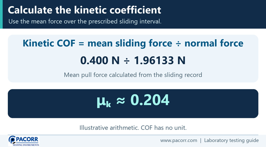
For a simplified teaching example, three equally weighted readings of 0.380 N, 0.400 N and 0.420 N have a mean of 0.400 N. An actual run uses the full data treatment required by the method. A few handpicked points cannot represent the full interval. Where the prescribed processing uses weighting or integration, retain that procedure and version with the trace.
What should you look for in the force trace?
Read the trace alongside the specimen and fixture behaviour. Initial tension typically rises towards the start of motion. Then the trace shows the force during sliding, which may be fairly steady or show fluctuations. The sliding interval is a defined window within that record. The setup and prescribed interval determine which data belong in each calculation.
| Trace feature | What to verify |
|---|---|
| Rise before movement | The line is tensioned according to the method, and the specimen remains seated. |
| Peak near first motion | Relative sliding begins at the event used for the static numerator. |
| Sliding region | The start and end of the required window match the controlled method. |
| Oscillations or isolated spikes | Check for real stick-slip, a wrinkle, fixture interference or recording problems. |
| Change near the travel limit | Review whether deceleration, stopping or fixture contact has entered the calculation interval. |
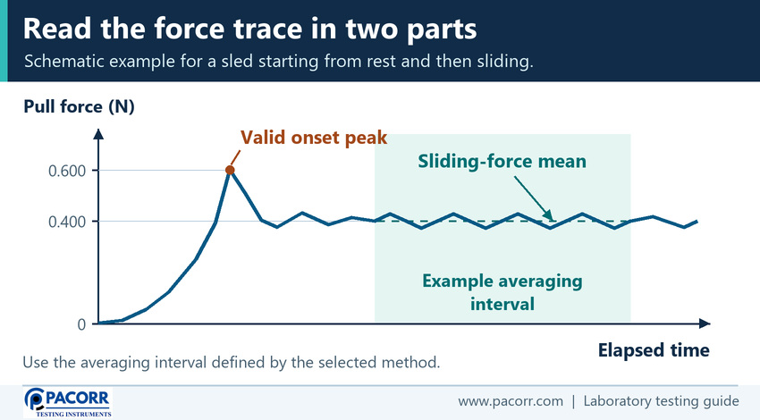
Repeated rises and drops can reflect alternating sticking and sliding. They can be meaningful for some surface pairs or come from the machine, mounting or drive arrangement. Investigate the cause before changing a calculation or excluding a run. If the controlled method provides special treatment for a trace shape, use that rule and retain the original trace. A smooth-looking average can conceal a problem that the curve makes visible.
What if the pull is angled or the load cell reads another unit?
A horizontal sled calculation assumes that the measured pull is parallel to the test plane. An upward angle introduces a vertical force component, reducing the normal reaction for a sled that stays in contact with the plane. A downward angle can increase it. The tension reading also contains a component that acts away from the sliding direction. Misalignment therefore affects both the force used in the numerator and the normal load in the denominator.
For example, with an upward pull at an angle θ above horizontal, tension T has a horizontal component T × cos θ and an upward component T × sin θ. With weight as the only other vertical load and no vertical acceleration, the normal reaction would be mg − T × sin θ. In established sliding at steady speed with no other horizontal loads, the friction force balances the horizontal component. This force balance explains the error. For a standard test, correct the physical alignment to the required setup and verify the run under the prescribed conditions.
Use a consistent force unit throughout. A display or export may use N, mN or a force unit such as gf. One newton equals 1,000 mN. If the starting force is 600 mN, use 1,961.33 mN as the example normal force or convert both to newtons. Dividing 600 by 1.96133 without converting introduces a thousandfold error. Confirm what a display marked “g” actually represents before using it as force.
Zero or tare the force channel as specified. That step establishes a valid baseline for the measurement system. It does not remove friction caused by a rubbing guide, an off-axis linkage or an obstruction. Check the force signal with the fixture mounted and follow the method for initial tension and contact before the recorded run.
Which surfaces, faces and directions should you test?
Enter the complete contact pair in the test request. For film-to-film testing, identify each specimen and the face presented to the interface. For film-to-metal or film-to-glass, document the counterface specified by the method, including its condition and relevant finish. A substitute surface can change the result even if the same film, load and speed are used.
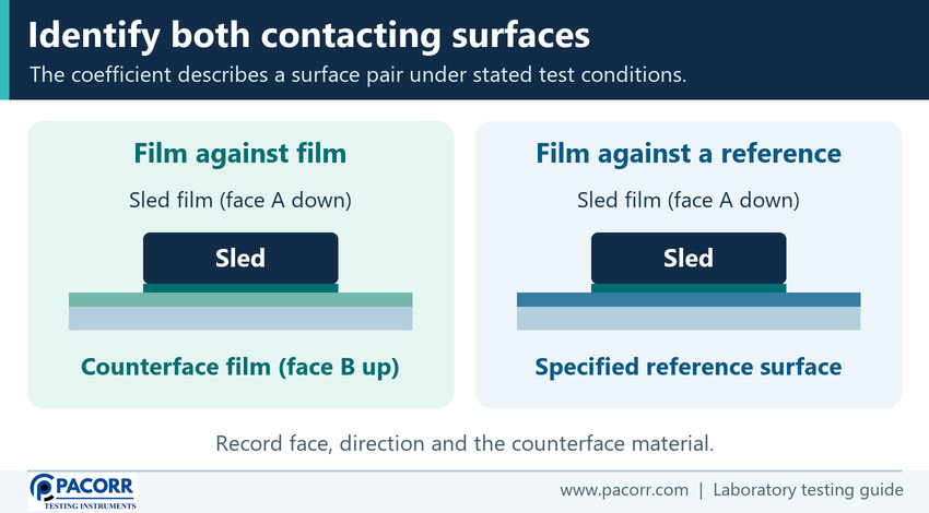
Cut the pieces in the required orientation. The machine direction, or MD, follows the web's production direction. The transverse direction, or TD, runs across it. Define how each piece is mounted and which way relative sliding occurs. A laminated film can also have a distinct sealant and print side. Record these identities before cutting or turning over the specimens.
Use fresh eligible contact tracks and surfaces as directed. Avoid fingerprints, wrinkles, dust, coating transfer and visible damage unless those conditions are part of the intended test. Hold the film flat without introducing an unintended strain. Handle and clean the counterface according to the approved method. A single numeric limit cannot resolve a disagreement about which face or track was tested.
How do conditioning, contact time and slip additives affect COF?
Keep test and conditioning conditions consistent. Temperature and specimen history can affect the surface response. In certain films, slip additives can migrate towards the surface over time and change how easily it slides. Keep the interval between manufacture, sample preparation and testing visible when comparing supplier lots or monitoring a new formulation. Avoid assuming all films change in the same direction or at the same rate.
The time the sled and plane remain in contact before motion can affect the starting result. The rate at which the force builds also matters. Where real production packs remain stacked or a roll sits under load, agree a separate application trial if the prescribed laboratory contact time cannot represent the question. Blocking, adhesion between adjacent layers, can influence the onset. A single static COF measurement does not quantify every blocking condition.
If a formulation change appears to move the average, use matched times, faces and directions before concluding that the material itself is responsible. Record storage and conditioning and compare trace patterns. When the required counterface or conditions differ between two laboratories, resolve those differences before pooling their data.
Do ASTM D1894 and ISO 8295 give interchangeable results?
ASTM D1894-24 covers the starting and sliding friction of plastic films and sheets against themselves or other substances under prescribed conditions. ISO 8295:1995 has a similar material scope and remains current following ISO's 2026 review. The ASTM scope explicitly distinguishes its method from ISO 8295 and states that results cannot be directly compared. ASTM D1894-24 scope and ISO 8295:1995 scope.
| Method decision | What to confirm |
|---|---|
| Customer specifies ASTM D1894 | Confirm edition, required contact pair, arrangement, conditioning, speed, data selection and reporting. |
| Customer specifies ISO 8295 | Apply its apparatus and test provisions and retain that method identity with the values. |
| Supplier reports a different method | Agree how to compare it or retest using the specified method before judging conformity. |
| Material falls outside film and sheet scope | Choose the procedure appropriate for the material and application. |
The ratio of tangential force to normal force is shared physics. The procedures define how to obtain each force result. When a lab changes methods, compare matched specimens and identify the effect before treating the results as the continuation of a single trend. A product listing that mentions both standards is a starting point for a configuration discussion. Check the full method and qualifying evidence for the machine and fixture you will actually use.
How do you run a coefficient of friction test?
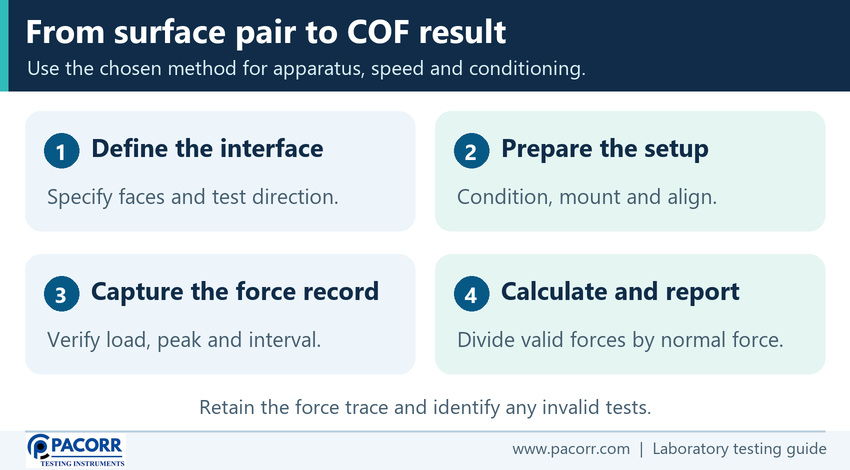
Use the following sequence to plan and review a film test. Take specimen sizes, speeds, travel, contact timing, valid test count and detailed operating requirements from the selected method and equipment instructions.
- Identify the lot, surface pair, faces, slide direction, method and edition. Confirm which coefficient or coefficients the customer needs.
- Condition and mount the specimens as specified. Prepare a suitable counterface and record the required sample age or storage history.
- Verify instrument status, loaded sled arrangement, level, line of pull and display units. Apply the prescribed zero and fixture checks.
- Bring the surfaces into contact as directed. Start the test under the prescribed settings and capture the force trace and movement information.
- Review the valid onset and sliding interval. Record any slip in the mounting, wrinkle, interference or other deviation. Apply the method's rules for repeating affected runs.
- Calculate μs and μk from the respective forces and justified normal load. Keep the original units, individual results and trace reference.
- Summarise the results for the correct sample group and apply the agreed decision rule. Keep observations, exclusions and retests traceable.
During method setup, run representative low-force samples as well as typical material. Verify that the load cell and data system can distinguish the expected changes and capture a short onset event. Check speed and travel separately from force. A peak reading can look sensible even if it is flattened by inadequate sampling or if the approved sliding interval has been set incorrectly.
What causes unusually high, low or scattered COF results?
Start with the record. Compare the units, loaded sled assembly, selected data windows and the method used to calculate each value. If the force trace is unchanged but the COF shifted, check the normal load saved in the instrument software and whether the report is reading the same force column. One incorrect load entry can affect all calculated coefficients in a batch.
Next compare the specimens. An orientation change can show up as a different sliding pattern. Dust or film transfer can build up over consecutive runs. Mixing the sealant and printed sides can split a set of results into two groups. Trace each result to its face, orientation and track before deciding whether an apparent outlier is invalid. Document a physical or procedural reason when the method allows exclusion.
If the force rises abruptly before the sled reaches the expected point, inspect the line, specimen mounting and clearances. If it drifts gradually through the sliding window, review specimen uniformity, the condition of the track and the movement of the fixture. Preserve the original file and any repeated measurements. Compare matched reference samples or representative material across instruments before attributing every difference to a new film lot.
Is there a good COF range for every packaging film?
The right range depends on the task and the contact pair. For a fast-moving film on a forming surface, low sliding resistance may help feed consistency. In a stack, too much slip at the relevant surface pair may allow packs to shift. Higher starting resistance can be useful in some cases, yet it may complicate separation or feeding in another. Evaluate the friction results against the intended operation.
Set purchase limits with the customer, specifying the test method, faces, direction, sample condition, valid count and decision rule. The method shows how to measure. The application determines what is acceptable. When qualifying a new film, pair the laboratory result with a representative machine or handling trial. ISO 8295 is primarily a quality-control method and its scope does not present a comprehensive machinability assessment.
Use complementary measurements for separate problems. Tensile testing assesses how a film deforms under tension. Heat-seal preparation and seal strength assess joining, while COF assesses contact resistance to starting and sliding. A film can meet its COF target while needing stronger seals or different tensile behaviour. Pacorr's guide to testing films and laminates, plastic film tensile method comparison and laboratory heat sealer guide.
How can static and kinetic COF guide a production investigation?
Suppose a bag converter notices that a line hesitates at restart, then moves the web steadily. Compare the starting peaks and sliding regions for samples from the last acceptable roll and the affected roll. Use identical faces, counterface, direction, contact history and test settings. If the starting peak changes while the sliding region remains similar, the next investigation can focus on what happens during initial contact or after a stop. Review dwell, film age and the handling of those surfaces before changing the film specification.
If the entire sliding region changes, check whether the affected surface or the machine contact itself has changed. Inspect the process for contamination, guides and alignment before attributing the problem to COF alone. A laboratory trace helps narrow the investigation. The line also has web tension, guide geometry and settings that the sled test does not reproduce. Use a representative trial to assess the proposed change and carry only the validated conditions into the quality plan. Pacorr's overview of flexible packaging quality tests.
What should a COF test report include?
Record the method and edition, sample identification, both contact surfaces, the directions and condition, instrument and configuration, required conditions and individual valid results. Identify the force unit, normal load, start-event rule and sliding data interval. If the report uses software calculations, store enough settings and raw data to reproduce the results.
| Record item | Illustrative result or description |
|---|---|
| Surface pair and direction | Identify both faces or counterface and the direction of sliding. |
| Normal load | 1.96133 N as the arithmetic intermediate for the fictitious loaded mass. |
| Static result | 0.600 N at valid onset, giving μs ≈ 0.306. |
| Kinetic result | 0.400 N mean over the defined sliding interval, giving μk ≈ 0.204. |
| Trace and decisions | Save the force record, valid count, relevant deviations and agreed acceptance rule. |
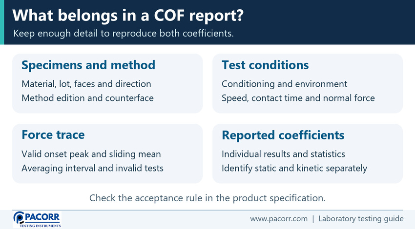
The displayed decimal places do not establish accuracy. Follow the prescribed rounding and report precision, particularly near a limit. If the rule applies to an average, retain the individual values and valid count so the reviewer can still see variation. Keep results for different pairs, directions or test conditions in separate groups.
What does Pacorr publish for the PCCOF-D and PCCOF-C?
The product page identifies the digital model as PCCOF-D. Its listed details are below. Confirm the configuration, matched accessories, applicable method and usable calibrated force range for the intended test.
| Published feature | PCCOF-D listing |
|---|---|
| Load cell capacity | 1 kgf, or a configuration agreed for the requirement. |
| Sled | Nominal 200 g and 63.5 × 63.5 × 6 mm. |
| Test plane | Moving stainless steel platform with guides, glass plate and specimen clamps as listed. |
| Display and drive | Digital controller with peak memory and LCD speed indication. A fixed-speed drive is listed. |
| Electrical supply | 220 V, 50 Hz. |
The catalogue sled mass alone does not establish the delivered assembly's normal load for every method. The numerical drive speed and the details of the data reduction should be confirmed for the quotation. Ask for force resolution and accuracy with units, the actual verified range and any documentation needed for your quality system. Pacorr Digital Coefficient of Friction Tester.
The separately listed PCCOF-C computerized model describes RS-232 computer connectivity and graphical results. If trace export or audit records are required, confirm exactly what the machine and software provide, including raw force units, travel or time data, supported averaging controls and compatibility with your computer. Pacorr Computerized Coefficient of Friction Tester.
Frequently asked questions
What is the static coefficient of friction formula?
Divide the valid force for the onset of sliding by the normal force. Use matching force units and select the onset event according to the test procedure.
What is the kinetic coefficient of friction formula?
Divide the mean sliding force over the interval prescribed by the method by the normal force. The reported ratio is dimensionless.
What is the normal force for a 200 g sled?
For an illustrative loaded mass of 0.200 kg on a horizontal plane with a horizontal pull and no other vertical forces, standard gravity gives 1.96133 N. Verify the applicable assembly and normal load in an actual test.
Does COF have a unit?
No. The force in the numerator and the normal force in the denominator use the same unit, which cancels. Record the original force units separately.
Should I always use the highest peak as static COF?
Use the method-defined valid starting event. A later peak, slack take-up or impact can produce a higher reading that does not correspond to the start of sliding.
Can ASTM D1894 and ISO 8295 readings be compared directly?
The ASTM scope states that the methods are not equivalent. Report the method and edition and use the specified procedure for a direct comparison or acceptance decision.
Do the inside and outside faces of a film have the same COF?
They can differ because of the surface construction and treatment. Specify the faces, counterface and sliding direction before testing.
What can cause the kinetic force to fluctuate?
Stick-slip, surface variation, wrinkles or fixture and drive effects can produce fluctuations. Review the trace and the setup, then apply the approved data and validity rules.
Is lower COF always better?
The preferred range depends on the contact pair and use. Feeding, sliding and stack stability can call for different friction behaviour. Use limits tied to the application and test method.
Can I use 0.306 and 0.204 as film acceptance limits?
Those numbers are worked examples. Use the customer or material specification to determine the actual limits, conditions and decision rule.
How can Pacorr help you specify a COF tester?
Send the film or sheet construction, surface pair, faces, sliding direction, test standard and edition, expected force range, sample throughput and reporting requirements. If you need force graphs, send the file format and event or interval details your laboratory requires. This helps Pacorr discuss the suitable machine, sled and counterface configuration. Contact Pacorr for a test configuration and quotation.