
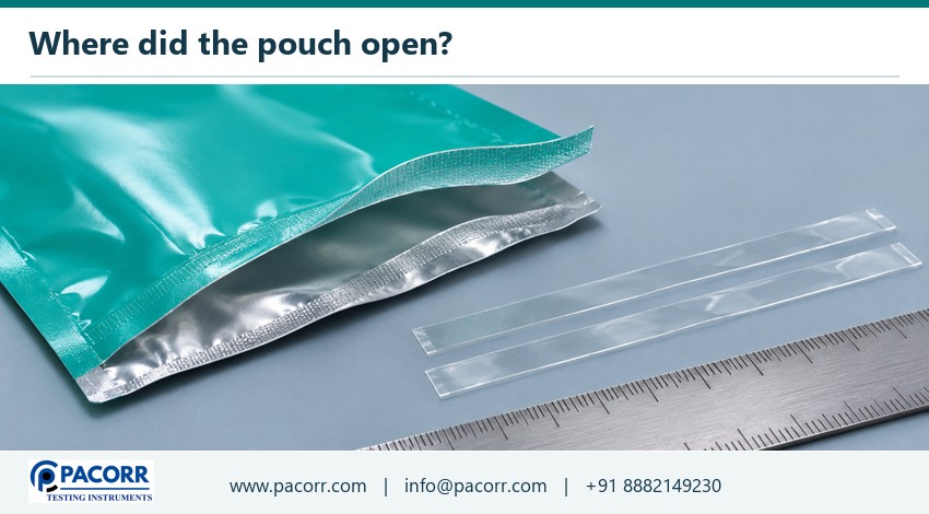
A pouch has opened along the top edge, yet the retained roll passed its tensile test. Both observations can be true. A strip of film pulled lengthwise carries force through its full cross-section. A seal strip pulled by its two tails can open along a bond, separate between laminate layers, or tear through the film beside the bond. The first question for a returned pouch is where the opening began. The answer determines which sample to cut and which result can explain the complaint.
Start with one unopened companion pack if one is available, one failed pack left as received, and a sketch showing the suspected origin. Keep three records distinct throughout the investigation: what happened in service, what happened when someone opened the return, and what happened on the testing machine. A photograph taken before handling can be more valuable than an extra force reading taken after the original opening has been disturbed.
Read the opening before cutting the pouch
Lay the return on a clean contrasting surface. Photograph the whole front and back with the pouch upright and the lot code readable. Take a second photograph with a scale beside the suspected origin. Record which edge faced the product, which end was filled last, and whether the damage lies at a straight seal, corner, gusset or intersection. An operator's left side and the customer's left side may be opposite. A photograph labelled with the print face and filling direction gives both teams the same reference.
Look at the two separated faces together. A smooth region that follows the seal interface suggests the seal opened there. Material transferred to both faces can point to tearing within the sealant. A broad lifted ply extending beyond the sealed band shifts attention towards the laminate construction. A narrow slit just outside the band leaves yet another possibility: a notch, fold or thinned wall beside an otherwise sound bond. Describe colour, surface texture and the path of the opening before assigning a cause. An opaque ink layer can hide the interface that actually separated.
A long opening may contain several modes. A tear can start at a small edge defect, run along a seal, and then turn into the wall when the pack is handled. Mark the first point the available evidence supports and indicate any uncertain segment with a separate line. Ask whoever discovered the pack whether they pulled the faces apart to see inside. That observation often explains why a neat, long peel appears beside a much smaller, irregular leak path.
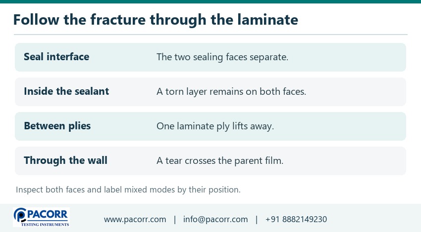
Match each suspected failure to an observation
| What you see | What to compare next | What the comparison can establish |
|---|---|---|
| Two seal faces separate cleanly | Matched seal strips from the same position on intact packs | Whether separation at that interface recurs under a controlled pull |
| One laminate ply lifts beyond the seal | Both fracture faces and retained unsealed laminate | Whether separation follows the same layer boundary away from the seal |
| Film tears close to the band | Wall strips, edge condition and the transition beside the seal | Whether a local defect or loss of section deserves investigation |
| Film tears far from any seal | Wall specimens in both known web directions and any visible marks | Whether orientation or local damage follows the tear pattern |
| A filled pack leaks through a short channel | An intact companion with its leak location mapped | Whether the detected path crosses the sampled part of the seal |
A recorded mode describes how that specimen ended. It does not establish which process setting caused it. For instance, two cleanly separated tails may have been made with the wrong contact conditions, with product caught in the seal, or with the intended peelable construction. The material specification and an accepted reference pouch help distinguish a designed peel from an unexpected one. Compare comparable surfaces under the same lighting before calling one clean and the other contaminated.
Preserve loose fragments separately and label which face they came from. If a printed ply lifts, trace the exposed layer into an undamaged area before identifying it as the cause. A failure analyst may need the supplier's layer sequence to identify that interface reliably. Pacorr's guide to mechanical tests for poly films and laminates provides background on the different properties measured across a laminate.
Cut matched seal and film specimens
First mark the available material on a drawing. Give each pack an identifier, then give each sampling position a suffix. For example P04-L can denote the left end of the top seal on pack four. Mark machine direction and transverse direction from traceable web information where available. The long edge of a converted pouch does not always follow the machine direction. When orientation cannot be traced, report the physical direction along or across the pouch and retain the uncertainty.
Cut seal specimens across the band so each has two usable tails in the orientation required by the chosen method. Record actual specimen width. Separate samples from the left, centre and right of the same seal when the available geometry permits. A gusset transition or a side-seal intersection may have extra layers. Treat it as its own location and state its construction. Combining those numbers with a straight two-layer seal can bury the only relevant pattern in a plausible-looking mean.
Cut film controls from an intact, flat wall away from folds, graphics damage and the heat-affected edge for the baseline measurement. Take additional specimens near the suspect feature and identify their location separately. If there is enough material, cut strips in both known directions. Inspect cut edges for nicks and measure the original thickness according to the applicable method. Keep a record of any specimen that cannot meet the agreed geometry. A short, irregular coupon may support a diagnostic observation while being unsuitable for a specification result.
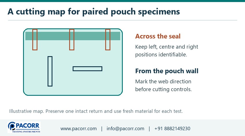
Two strips cut next to each other describe local repeatability. Several packs taken at different points in the filling run answer a wider question about the lot. Preserve both levels in the worksheet. Five strips from one pouch should retain one pack identifier and five strip identifiers. If the only material is a single failed return, ask for retained packs or the corresponding web before making a statement about production as a whole.
Run a seal-strength test with a defined setup
Use the procedure and revision agreed in the pack specification. The official ASTM F88/F88M standard for seal strength of flexible barrier materials is a relevant starting point. Identify the selected tail-support technique, specimen width, test speed and conditioning on the worksheet. The way the free tail bends during separation can affect measured force. A change of support between the supplier's trial and the converter's trial can change the recorded value even when the seal construction is unchanged.
Align the specimen so the opening advances across the strip as intended. Check that the tails remain held without slipping and that the grip faces do not introduce a fresh cut. Keep the force trace and examine the specimen immediately after the run. Pacorr's guide to peel strength testing on plastic films is relevant when identifying the grip arrangement and recording how the separation travelled. Photograph a representative good strip as well as a questionable one.
Identify whether the result is a maximum force or an average over a defined part of the opening. An initial peak may correspond to getting a peel started. A later sustained region may describe continued opening. Select the result defined by the method or agreement and apply the same selection rule to all runs. If the wall tears after the initial peak and before sustained peeling occurs, preserve the peak as an observation and flag the missing sustained region. An average manufactured from the remaining tail movement would describe the wrong event.
Measure what the free film contributes
A free-film tensile test answers whether material cut from the pouch wall carries and stretches under a defined uniaxial load. Select a suitable method for the film and its thickness. Pacorr's comparison of plastic and thin-film tensile methods covers geometry, direction and reporting. Keep the same reference length, strain measurement route and test settings when comparing the suspect film with accepted material. Record whether each break occurred in the intended test region.
Inspect both peak force and the shape of the extension record. A sharp edge nick can shorten extension markedly on the affected strip while neighbouring undamaged material behaves normally. A difference that repeats across independently cut strips and across packs carries more weight than one unusual break. Place the cut specimens back beside their sample map after the test. A cluster of short extensions on one side of a web suggests a different follow-up from a direction effect seen across the entire web.
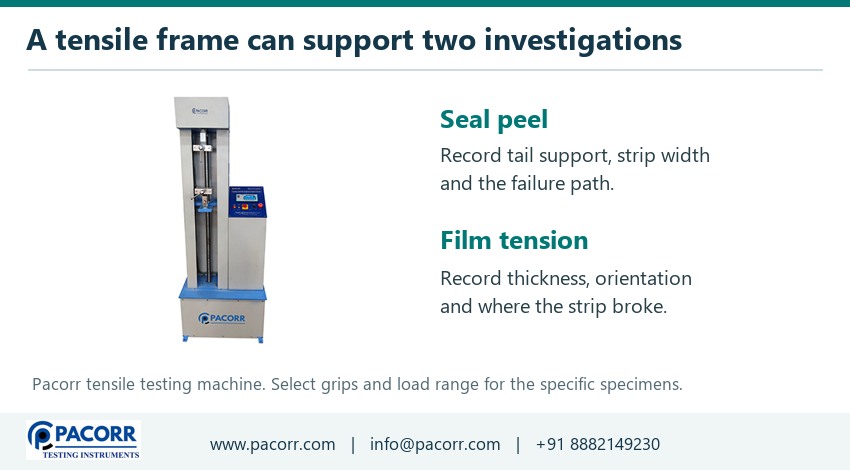
The Pacorr digital-cum-computerised tensile testing machine is a relevant equipment option when a team needs to review individual force records alongside specimen notes. Confirm load-cell range, grip faces, travel and the actual outputs for the configuration being considered. A frame shared between film tension and seal peel still requires the correct fixtures and a documented setup for each test. A saved setup name alone cannot tell a reviewer how a thin tail was supported during the run.
Read seal force and film stress in their own units
Consider an illustrative seal strip 15 mm wide with a maximum pull of 12 N. Its width-normalised value is 12 divided by 15, or 0.80 N/mm. The same observation can be written as 12 N per 15 mm when the reporting convention is explicit. Converting the unit allows readers to recognise equivalent expressions. It does not remove differences in tail support, specimen geometry, force statistic or opening mode. Record those alongside the number.
Now take an illustrative free-film strip 15 mm wide with a measured original thickness of 0.060 mm. Its original cross-sectional area is 0.90 mm². At a maximum force of 27 N the engineering tensile strength is 30 N/mm², equivalent to 30 MPa. Thickness enters the film calculation directly. If a worksheet silently uses 60 as millimetres when the gauge reported micrometres, the answer changes by a factor of one thousand. Carry units through the calculation and retain the source thickness readings.
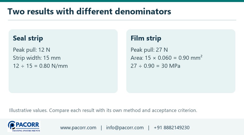
Which result is larger is the wrong question for these two numbers. A peel force divided by width and a tensile force divided by original area describe different quantities. Compare the seal result to a seal requirement using the same method, and the film result to its tensile requirement in the same direction. To investigate a complaint, compare the fracture path on the return to the fracture path in the test. The two valid numerical comparisons and the visual evidence together support a defensible conclusion.
Investigate a leaking pouch with a strong seal result
A narrow channel can cross the sealed band at one point while the rest of the band remains well bonded. A 15 mm strip cut several centimetres away can give an acceptable peel force. Both observations belong on the report. Start by localising the leak on an intact companion using an integrity method suited to the pack, its contents and the suspected defect. Document where the indication first appeared. Keep separate material for destructive mechanical testing whenever possible.
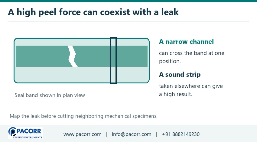
Once the location is mapped, compare specimens on either side of it with a specimen from a comparable sound location. Inspect for folds, product inclusions, edge damage and changes in layer count. A leak indication that repeats at the same gusset transition across several packs deserves a targeted comparison of that transition. Repeatedly testing the straight centre band may produce clean data while leaving the relevant geometry untouched. Pacorr's overview of leak test apparatus explains the integrity question behind a leak test.
Keep the detection conditions with the leak observation. Different methods respond to different paths and package designs. A channel that opens under flexing may close when the empty package lies flat. A liquid found near an edge could also have tracked there from another location. State which observation directly locates a passage and which merely shows where fluid was visible. If the leak could not be reproduced, retain that result with its conditions and record which part of the complaint remains unresolved.
Work through a returned pouch from start to finish
Imagine a converter receives three filled pouches from the end of one shift. Each has staining at the same top corner. Routine records show acceptable centre-seal peel on samples from that shift. The quality team first maps the returns against print registration and finds that the affected corner lies at the same gusset transition on all three. Two unopened retains show a local integrity indication at that transition. A third retain stays intact for later examination. These are illustrative observations, with no implied acceptance limits.
Fresh centre strips from several retains peel along the expected path. Strips near the transition often tear into the wall or expose a folded region. Flat wall controls from the same pouches behave similarly to accepted wall material when grouped by web direction. This evidence narrows the investigation to a local packing or sealing feature. It also explains why routine centre strips gave reassuring results. It does not yet distinguish a folded web from uneven jaw contact or product transferred into the corner.
The next trial marks the transition before sealing and records whether a fold enters the band on each pack. The team compares packs made with the original and corrected web guidance while keeping the material, sealer settings and filling conditions documented. Both the local integrity check and the position-specific peel observations are repeated on newly made pouches. If the indication follows the visible fold and disappears on repeated corrected runs, the conclusion becomes more specific. A later check under ordinary production conditions tests whether the correction persists after a changeover.
A different result would lead elsewhere. Suppose the returned openings start in the middle of a wall beside a hard product edge, the seals remain bonded and matched film strips meet their directional requirements. Increasing seal temperature would address little of the evidence. Reconstruct the product position, examine the contact mark and compare the interaction with accepted packs under representative handling. A material can meet the tensile specification and still be vulnerable to concentrated contact in a particular package design.
Decide what belongs in the investigation report
Write the opening sentence so a reader can picture the failure. For example, say that two of five retained pouches showed a channel at the print-side gusset intersection and that the adjacent centre-band peel strips opened normally. Then identify which observations were made on the return, which on retained packs and which on material made in a trial. Record specimen widths, film thicknesses, orientations, force statistic, setup details, failure modes and the photo identifiers. Report individual observations alongside the summary.
Include contradictory results. If four strips peel and one tears at the jaw, show the five outcomes with their validity assessments and the reason for any exclusion. If a specimen tears through the film beside a sound seal, the maximum force describes that failure in that setup. The interface's ultimate separation force remains undetermined. When an accepted reference pouch behaves the same way, that similarity matters for interpretation, especially in a deliberately strong permanent seal.
Record what decision the evidence supports. A localised diagnosis can justify checking a particular jaw position, inspecting web tracking or repeating a trial with matched material. A lot-release decision requires the agreed acceptance plan, representative samples and the relevant specification. Separate the production action from the planned confirmation. Assign the next reading to a named location and condition so the next shift can repeat the investigation without guessing which centre strip or corner the first operator meant.
Frequently asked questions
Can a strong film still make a pouch that opens at its seal?
Yes. Film tensile strength describes load carried through a specimen cut from the wall. A sealed pouch also depends on the surfaces brought together, their contact during sealing and local geometry. Compare a strip crossing the suspect seal with a strip from an accepted pack, then inspect where each one separates. A strong wall alone cannot establish continuity along the sealed band.
What if the film tears before the seal opens?
Report a substrate tear, its location, the recorded force and the setup. The test shows which part failed first under those conditions. It leaves the force needed to peel the intact interface unresolved. Inspect whether the break was at a nick, grip or seal transition, and repeat on independently prepared specimens as the method permits.
Can a burst result replace a seal peel result?
A whole-package pressure test loads the assembly through its shape, restrained or free surfaces, wall material and seals. It can help localise a weak region or compare finished packs under defined conditions. A cut-strip peel test examines a specified seal location under a defined opening geometry. Use the method specified for the decision and preserve the observed failure location in either case.
Should the quality team average left, centre and right measurements?
Keep each position visible first. A single overall mean can hide a repeatable low result or a different failure mode at one end of the jaws. A pooled value may be required by a particular reporting plan. Supply the positional results with it, together with the number of separate pouches represented at each location.
How can the lab tell delamination from a seal peeling open?
Trace the separating layer beyond the band and inspect both faces under consistent lighting. A ply that lifts beyond the original seal suggests an interlayer path. The known laminate sequence and an unsealed reference help identify which interface is exposed. Use a provisional description if pigment, transfer or an opaque layer prevents reliable identification by eye.
What should I send with a pouch for equipment or application review?
Provide an intact representative pack, the layer construction if known, strip width, expected force range, direction markings and photographs of the failure. Specify whether you need seal force, wall tensile properties, package integrity or a combination. Pacorr's application enquiry team can use these details to discuss a suitable instrument, grips and reporting configuration.
Recent Blogs
Enhance your understanding of testing and precise quality control indistinct applications with our
knowledge based articles coming from top editors of industry leaders.
Our USP's
Demonstration of Machine
- Try Before You Decide
- Experience Before You Invest
- See It in Action – Free Demo
Global Reach
- Delivering Excellence Worldwide
- Serving Across Borders
- Your Global Supply Partner
On-Site Support
- Support That Comes to You
- On-Ground Assistance, Anywhere
- We Reach Where You Are
Team Strength
- Powered by Expert Minds
- Driven by Skilled Professionals
- Engineering Excellence Team
Manufacturing
- Precision-Driven Manufacturing
- Smart & Automated Production
- Engineered In-House Excellence
