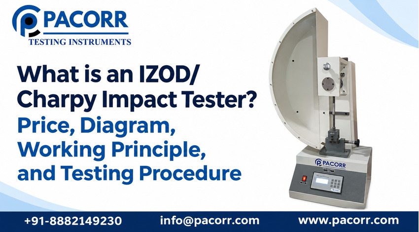
An IZOD/Charpy Impact Tester is a pendulum instrument that measures the energy associated with breaking a prepared specimen under a sudden bending blow. Izod holds the specimen as a cantilever, with one end clamped. Charpy supports the specimen at two locations and strikes between them. The mounting arrangement, notch orientation and reporting method must match the selected standard.
Specimen preparation, temperature, hammer selection, dimensions and failure classification determine whether a joule reading supports a material decision. This guide covers equipment, diagrams, calculations, testing and buying questions. Its procedures are educational; use the controlled standard and supplied machine manual for exact operating instructions.
What does an Izod/Charpy impact tester actually measure?
The instrument compares the pendulum's energy before impact with the energy remaining after it passes the specimen. Applicable corrections and the prescribed calculation turn this observation into a reported impact result. It is a destructive test: each valid impact uses a fresh prepared specimen.
Distinguish absorbed energy in joules from normalised impact resistance, which divides energy by the prescribed dimension or area. Peak force requires suitable instrumentation; one energy number cannot establish it. Check the formula, dimensions and units behind a controller's impact-strength display.
What is the difference between Izod and Charpy testing?
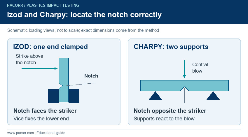
Both methods use rapid bending, but the specimen experiences different boundary conditions. In the usual notched Izod arrangement, a vertical specimen is secured in a vice and the blow acts on its exposed portion above the notch. The notch faces the approaching striker. In the usual notched Charpy arrangement, a horizontal bar rests against two supports and the striker acts opposite the central notch.
| Method | Mounting and loading arrangement |
|---|---|
| Notched Izod | One end clamped; notch towards the striker; blow above the notch. |
| Notched Charpy | Two supports; specimen centred; blow opposite the notch. |
| What both require | Controlled geometry, suitable hammer, correct alignment and a defined reporting basis. |
These descriptions concern the conventional configurations shown in the educational diagram. Unnotched tests and other specified arrangements need their own work instructions. Do not rotate a specimen or change a fixture and assume the original method still applies.
Which method should a manufacturer select?
Start with the customer's specification, drawing or qualification plan: its standard, specimen and temperature define the test. Otherwise, agree the purpose first—material comparison, formulation development, process monitoring or contractual acceptance.
A moulding supplier comparing lots needs a repeatable coupon and conditioning plan. Notch-sensitivity research needs controlled specimen comparisons. A dropped-enclosure investigation needs component testing alongside material data. One coupon number cannot answer all three questions; record the required output before specimen preparation.
Which materials and applications are suitable?
Plastics impact testing commonly supports work on rigid or semi-rigid thermoplastics, thermosets and suitable filled or reinforced materials, within the selected method's scope. Laboratories use prepared specimens to compare formulations, monitor moulding consistency and investigate changes after agreed conditioning or exposure. Applications include materials for housings, electrical fittings, automotive trim and other moulded components.
Prepare a representative specimen: a pellet cannot be tested directly in a bar-impact fixture. Flexible films, foams, assemblies and highly anisotropic composites may need another method. Confirm suitability from the material and standard rather than a claim of suitability for all polymers.
What does this test not establish by itself?
A coupon result does not establish product drop performance, allowable load or lifetime. Geometry, stress concentrations, fastening, temperature and loading can differ from the final component; compare results only within a technically relevant context.
Impact resistance is also different from tensile strength, hardness and a fracture-mechanics parameter such as KIC. Do not convert joules into a load-bearing rating without an appropriate mechanical model and validation. Pacorr's related guide to selecting plastic tensile tests explains a complementary measurement route. Use a set of appropriate tests to support the product decision rather than expecting one instrument to describe every failure mechanism.
Which components should you recognise in the instrument?
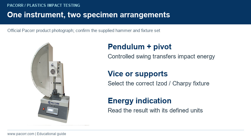
The system includes a rigid base and frame, pivot bearings, pendulum, striking edge, release mechanism, fixture and energy indication. Guards protect the operating space. Follow the machine's designed provisions for changeover, stopping and securing the pendulum.
The vice is central to Izod testing because it fixes the specimen's boundary. Charpy uses a support arrangement with controlled contact geometry and spacing. The energy indicator may use a mechanical scale or an electronic angle-sensing system. A specimen notcher is a preparation accessory, not automatically part of the impact frame. Ask which accessories, locating tools and protective features are included in the offered configuration.
How should the labelled setup diagram be read?
Follow the load path in each schematic. For Izod, the restrained end resists motion while the free portion bends under the striker. The notch lies near the restrained region, below the point where the blow is applied. For Charpy, the two supports react against the central blow, and the notch lies on the opposite face.
The simplified diagrams are not internal Pacorr drawings or fixture-manufacturing instructions. They distinguish notch orientation, striking location and clamp boundary; use the selected method for dimensions and tolerances.
What is the pendulum working principle?
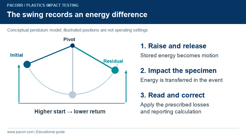
Raising a pendulum stores gravitational potential energy. On release, that energy becomes motion; some energy is transferred during impact and the pendulum rises to a lower height afterwards. Comparing the initial and residual energies provides the basis of the conventional measurement. The test uses the specified release condition rather than an operator pushing the hammer.
In a simplified model, the energy difference is E = mg(h1 − h2). Here m is the effective mass, g is gravitational acceleration, and h1 and h2 are corresponding centre-of-mass heights above the same reference. For a compound pendulum, the instrument's calibrated geometry and constants matter. Do not substitute the hammer's visible tip height or an estimated mass into a homemade calculation and treat it as a calibrated result.
Why are friction, windage and other losses important?
The observed swing loss is not purely the energy of creating a fracture surface. Bearings, air drag, indicating mechanisms, specimen deformation and machine motion can contribute. A loose base or a specimen that rubs against the striker after breaking can change the reading without representing an improved material property.
Use the prescribed checks and corrections for the selected machine and method. A safe no-specimen swing check helps monitor baseline behaviour, but it does not validate every mechanical feature. Investigate an unexpected change before adjusting compensation to make the display look normal. For low-energy specimens, a small absolute baseline error can be a large fraction of the result. Retain the correction status with the raw reading so the calculation remains traceable.
How should hammer energy capacity be selected?
Select a hammer that produces a valid test within the method's usable energy range. An undersized pendulum may fail to complete the required event. An unnecessarily large capacity can make a small energy difference difficult to determine with adequate relative performance. The best choice therefore depends on the specimen, expected result and verified system capability.
Do not interpret a listed 0–25 J range as proof of reliable measurement arbitrarily close to zero. Ask for each available hammer configuration, its nominal energy, suitable measurement range, resolution and verification evidence. Where approved incremental weights are used, follow the manufacturer's configuration and identification procedure. Changing the release angle to compensate for the wrong hammer also changes the impact condition; it is not a substitute for selecting the correct setup.
How do release angle and impact velocity affect the test?
Release angle helps define the pendulum's starting condition, but the angle alone does not specify the complete impact event. Pendulum geometry, mass distribution and striking arrangement also matter. Two machines described with the same angle are not automatically equivalent, and a high-energy hammer does not necessarily represent a higher striking speed.
Record the hammer and configuration, not just the angle. Confirm required velocity and geometry with the supplier. Use the release mechanism without an extra push; changing fall height to obtain a preferred result invalidates comparisons.
Which standards apply to plastic Izod and Charpy tests?
Use the full designation and edition required by the contract. The following official listings were checked on 16 November 2026. A software menu labelled ASTM or ISO does not by itself establish conformity to a specific method.
| Standard | Scope relevant to method selection |
|---|---|
| ASTM D256-26 | Notched Izod pendulum impact resistance of plastics. |
| ASTM D6110-26 | Charpy impact resistance of notched plastic specimens. |
| ISO 180:2023 | Izod impact strength under defined specimen and test configurations. |
| ISO 179-1:2026 | Non-instrumented Charpy impact testing of plastics. |
| ISO 13802:2025 | Verification of plastics pendulum impact machines. |
ASTM and ISO results should not be treated as interchangeable merely because both describe Izod or Charpy. Specimen geometry, reporting conventions and other requirements can differ. Retain the applicable material specification and any agreed departures with the test record.
Which similarly listed standards must not be confused?
Some standards support a laboratory without defining this impact test. ASTM D883 concerns plastics terminology, while ASTM D1204 addresses dimensional changes of thermoplastic film or sheeting at elevated temperature. Neither should replace the applicable Izod or Charpy procedure in a test request.
Likewise, ASTM D4812-25 concerns unnotched cantilever-beam impact resistance. It is not an alternative name for the notched Charpy method. If a brochure, purchase order and material datasheet use different designations, resolve that mismatch before testing. This small documentation check prevents ordering equipment or reporting data against the wrong property.
Can the same machine automatically test metals?
No. The shared words Izod and Charpy do not establish that a plastics pendulum machine can perform a metal test. ASTM E23 addresses notched-bar impact testing of metallic materials. Required energy, striker geometry, supports, specimens and verification arrangements must suit that method.
This article focuses on plastic specimens. For metals, obtain a separate configuration review; a swinging hammer and shared method name do not prove that a plastics tester covers steel.
What is the difference between analogue, digital and instrumented testers?
Analogue and digital conventional testers can both determine energy from the pendulum's motion. A digital display may simplify dimension entry, unit selection and result storage, but the display technology alone does not guarantee improved uncertainty or correct specimen setup. Ask how the result is derived and which corrections are applied.
An instrumented impact system additionally measures a time-resolved force signal with suitable sensing and acquisition. ISO 179-2:2020 covers instrumented Charpy impact testing. Such data can support a more detailed interpretation of the event, subject to the method's requirements. Do not describe an electronic angle display as a force-time instrument or promise peak-force data from a conventional energy-only system.
How should test specimens be prepared and identified?
Specify whether bars will be moulded, machined from a plaque or taken from a product. Each route answers a different sampling question. A separately moulded bar may characterise a controlled material state; a part coupon may reflect local processing, orientation and defects.
Record grade, lot, source and preparation date; identify flow or sheet direction before cutting. Avoid machining heat, damage and identification marks in the test region. Inspect surfaces before notching and retain the controlled specimen drawing or designation, including dimensions and tolerances.
Why do notch depth, tip radius and finish matter?
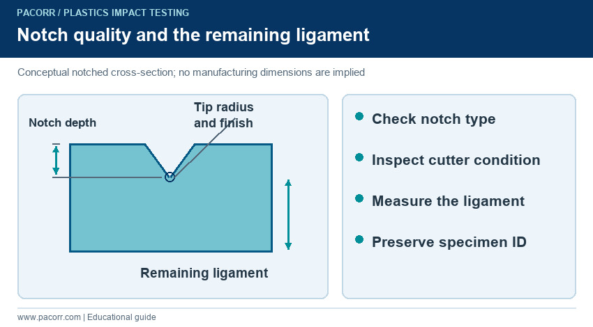
A notch creates a controlled stress concentration. Its depth changes the remaining ligament, while the tip shape influences how stress is concentrated locally. Two specimens with similar external dimensions can therefore behave differently if their notches differ. A rough cut, chipped edge or worn cutter can become a preparation problem disguised as material variability.
Use a suitable notching device and inspect the required geometry with appropriate measuring equipment. Confirm the notch type, remaining ligament, tool condition and preparation-to-test timing required by the procedure. Do not treat every V-shaped groove as equivalent, and do not sharpen a notch by hand to encourage a break. The notch illustration is conceptual; it explains which features matter without replacing a controlled specimen drawing.
Which dimensions belong in the calculation?
Identify each dimension by its physical direction and the selected standard's terminology. Width, thickness, specimen depth and remaining depth beneath a notch are not safe interchangeable labels. A controller may use its own field names, so the operator must confirm which measured dimension belongs in each field.
For an area-normalised notched result, use the relevant remaining ligament area, not automatically the original area. For a width-normalised result, use the method-defined dimension. Check units before transferring measurements and include a labelled sketch beside entry fields to prevent ambiguity.
How should conditioning and test temperature be controlled?
Polymer response can depend on temperature, moisture history and the time between preparation and impact. Apply the environment and duration specified for the material and method; avoid assigning one universal conditioning recipe to all plastics. ASTM D618 provides conditioning practices for plastics, while the applicable material specification may define the required state.
Record conditioning and actual test conditions separately. For testing away from room temperature, manage specimen transfer and timing so the intended condition is maintained as required. A chamber setpoint is not automatically the specimen's temperature at impact. Keep dry, conditioned, aged and as-received groups separate; otherwise a comparison can combine different material states and hide the reason for a change.
What should be checked before the first specimen?
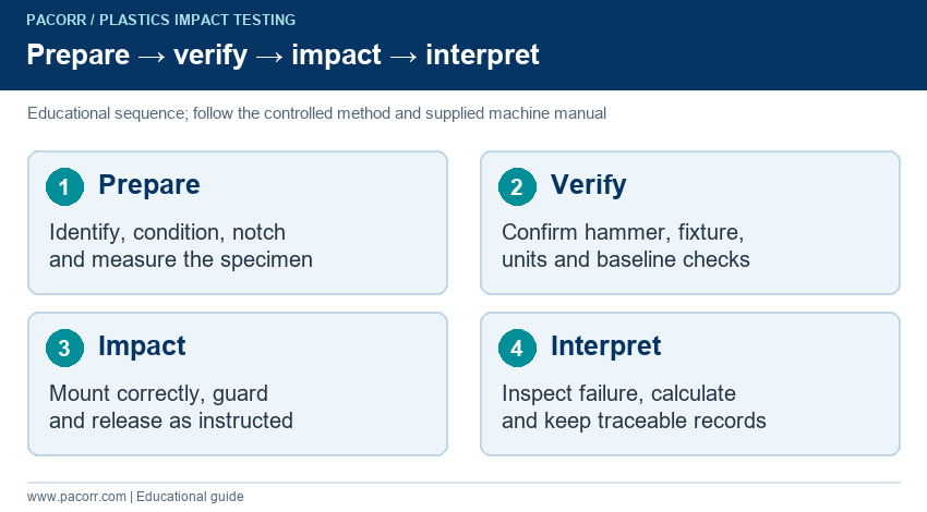
Confirm method, material, specimen identity, required result and configuration. Check installation, fixtures, hammer identity, release mechanism, guards and interlocks. Follow the manual for securing the pendulum and performing baseline checks.
Record dimensions, conditioning, hammer capacity, corrections and operator. Inspect the first specimen and its notch direction; verify controller units and method settings. Resolve fault indications before loading specimens rather than accepting unchecked readings.
What is an educational Izod testing procedure?
Use this sequence to develop a laboratory work instruction, then add the exact dimensional, clamping and operating requirements from the controlled method and model manual.
- Confirm the standard edition, material specification, specimen type and required conditioning.
- Inspect the prepared specimen and notch; record the required measured dimensions and orientation.
- Confirm the approved hammer, vice, striking arrangement and controller settings.
- With the pendulum safely secured as instructed, position the specimen vertically in the vice.
- For the conventional notched arrangement, face the notch towards the striker and set its position relative to the clamp correctly.
- Apply the specified clamping procedure; verify that the blow will act at the required height above the notch.
- Complete the guarding and release sequence using the machine controls, without adding a push.
- Record energy and observations; secure the pendulum before examining fragments.
- Classify the failure and apply the method's validity and reporting rules before calculating the group result.
Do not strike the same damaged specimen again to obtain a higher or more complete result. A repeat investigation requires a fresh identified specimen and a recorded reason.
What is an educational Charpy testing procedure?
Charpy needs its own fixture and alignment review. Reusing an Izod controller program without changing the physical setup and reporting definition can produce an apparently plausible but unsuitable value.
- Confirm the required Charpy method, edition, notch condition and specimen orientation.
- Inspect and measure the specimen after the required preparation and conditioning.
- Verify the approved hammer, striking edge, support geometry and support spacing.
- Secure the pendulum for setup and place the specimen against both supports without twisting.
- Centre the required impact location between the supports; in the conventional notched configuration, place the notch opposite the striker.
- Enter the correct dimensions, units and correction settings for that method.
- Close the protective system and perform the prescribed release sequence.
- Record the result, then safely secure the machine before collecting and examining fragments.
- Evaluate completeness of break, abnormal contacts and test validity before accepting the measurement.
A bar that slips, is wrongly centred or contacts the machine unexpectedly needs investigation. Do not edit the recorded result to resemble the neighbouring specimens.
How do joules, J/m and kJ/m² differ?
Joules describe energy. J/m describes energy divided by a specified length. kJ/m² describes energy divided by a specified area. These are different dimensions, not interchangeable display formats. The relevant method determines the denominator and the reporting convention.
| Quantity | Correct interpretation |
|---|---|
| J | Corrected energy for the specified event. |
| J/m | Energy divided by the prescribed specimen dimension in metres. |
| kJ/m² | Energy divided by the prescribed area, converted to kilojoules per square metre. |
| N | Force; not obtained directly from a conventional energy reading. |
ASTM D6110 reports a width-normalised result; ISO plastic impact methods use defined area-based quantities. D256's public scope recognises reporting per unit width or per area beneath the notch. Always state the exact basis. A bare number such as impact strength 20 is insufficient for a technical comparison.
Can you show a worked impact calculation?
Consider an illustrative corrected energy of 0.80 J and a method-defined normalising dimension of 4.0 mm. Converting the dimension to 0.004 m gives 0.80 / 0.004 = 200 J/m. This demonstrates a width-normalised calculation; the example is not a standard specimen prescription or an acceptance value.
For a separate area-normalised illustration, suppose the relevant remaining ligament is 8.0 mm and the other section dimension is 4.0 mm. The area is 32.0 mm². The calculation is 1,000 × 0.80 / 32.0 = 25.0 kJ/m², because 1 J/mm² equals 1,000 kJ/m². These two calculations do not establish equivalence between ASTM and ISO tests: they only demonstrate units and denominators.
As a correction example, a gross difference of 0.86 J minus an applicable 0.06 J loss gives 0.80 J. Apply only the correction authorised for the instrument and method; do not subtract an arbitrary blank value twice when the controller has already corrected the result.
Is least count the same as accuracy?
No. Least count or display resolution describes the smallest displayed increment. Accuracy, measurement uncertainty and usable range describe different aspects of performance. A screen showing two decimal places does not prove that the last digit is reliable throughout every hammer range.
For illustration, a 0.01 J increment is 5% of 0.20 J but only 0.5% of 2.00 J. This is an arithmetic demonstration, not a specification for Pacorr's tester. No verified least-count or accuracy value was available in the reviewed product data, so request it for the quoted configuration. Ask how resolution, baseline losses and verification uncertainty affect the lowest expected specimen energy.
How should complete, incomplete and non-break results be handled?
Inspect the specimen as well as the display. A complete separation, a hinged specimen and a specimen that remains largely intact represent different outcomes. ASTM D256 distinguishes complete, hinge, partial and non-break categories; apply its precise definitions and grouping requirements from the controlled edition. Do not pool unlike failure categories into a single convenient average.
ASTM D6110 requires a complete break for its standard result. If the required break is not achieved, retain the observation and identify the limitation rather than reporting an ordinary value as though the event were complete. A non-break does not mean zero impact resistance, infinite toughness or automatic acceptance. Check whether the specimen, method and available hammer range are suitable before deciding the next investigation.
Can Izod and Charpy results be converted directly?
There is no universal conversion factor. Clamping, support geometry, notch condition, specimen dimensions and loading details influence the response. Converting units does not transform one experiment into another. Even specimens made from the same named polymer can differ because their preparation and material histories differ.
For a supplier comparison, request the complete method designation, specimen configuration, conditioning, temperature, normalisation and failure category. For an instrument change, use a planned comparison with traceable material and appropriate statistics. Keep the original methods identified in the report. Do not create an empirical equation from a few unrelated datasheet values and present it as a generally valid relationship.
How many samples and what statistics should be reported?
Take the specimen count and acceptance rule from the governing method and specification. Repeating a calculation on one result does not create additional test specimens. Define how the lot is sampled, which orientations are represented and how preparation defects will be handled before testing begins.
Retain individual valid results and the requested summary statistics. Investigate scatter using specimen preparation, conditioning and failure observations instead of immediately blaming the material. A low reading is not by itself a valid reason to delete a specimen. Agree whether the product requirement applies to a mean, individual minimum or another measure, and how borderline outcomes are treated. There is no universal pass/fail energy for every plastic application.
How can impact testing support moulding and recycled-material investigations?
A controlled impact comparison can reveal a change worth investigating, but it does not identify the cause alone. Resin mix, contamination, moisture state, filler distribution, processing history and specimen orientation are possible investigation variables. Design comparisons that change one defined factor at a time wherever practical.
For example, keep specimen preparation and conditioning constant while comparing identified production lots. If the result shifts, review the process and examine complementary evidence before assigning a cause. Keep recycled-content levels and any blending records traceable. Impact data can support a quality-control decision; it cannot independently quantify recycled content, identify a contaminant or prove a particular degradation mechanism.
What common errors change the measured result?
Photograph abnormal fractures and retain their readings, dimensions and setup details. Investigate repeated patterns as well as individual outliers.
| Observation | Checks to prioritise |
|---|---|
| Excessive scatter | Notch quality, dimensions, preparation, conditioning and alignment. |
| Unexpectedly high energy | Wrong unit or denominator, double correction, abnormal rubbing or specimen restraint. |
| Repeated incomplete breaks | Method suitability, specimen condition and available hammer energy. |
| Baseline swing changes | Bearings, indicating system, contamination, contact or installation condition. |
| Differences after changeover | Hammer identity, fixture geometry, selected program and correction state. |
Record the diagnosis and any corrective action. If a machine component is damaged, stop using that configuration until it has been assessed and the necessary checks completed. Do not conceal a mechanical fault by modifying the sample dimensions entered into the controller.
What calibration and verification evidence is useful?
Verification should address the installed measurement system, not only its display. Relevant checks can include pendulum properties, striking geometry, fixture alignment, support or clamp dimensions, baseline losses and indication. The applicable procedure defines what must be checked and the permitted limits.
ISO 13802:2025 concerns verification of plastics pendulum impact machines, including checks after installation, repair, relocation and at prescribed intervals. Its scope does not cover force/work verification of instrumented systems. Request records identifying the machine, hammer configurations, method, results and traceability. A certificate for one configuration should not be assumed to cover every optional hammer or fixture. Use the governing requirements and documented stability when setting the laboratory's verification programme.
How should the tester and notching system be maintained?
Keep the machine and specimen-contact surfaces clean, and inspect accessible fixtures for wear or damage under the manufacturer's safe maintenance procedure. Monitor baseline behaviour and retain service records. Treat the notcher, dimensional gauges and specimen-locating tools as part of the testing system because their condition can affect the result.
Do not lubricate, adjust bearings, reshape a striking edge or modify a guard without the specified service instruction. After a repair or a significant setup change, complete the applicable checks before returning to routine work. Store detachable hammers and accessories so their identity and contact surfaces remain protected. Routine care supports repeatability but does not replace scheduled verification.
What practical safety controls are needed?
A raised pendulum stores energy and broken specimens can generate fragments. Keep people clear of the swing path, use the protective system provided, and follow the manual for safe loading, release and stopping. Secure or isolate the pendulum as instructed before changing fixtures, collecting fragments or carrying out maintenance.
Do not reach into the test zone because the display has stopped updating; physical motion and stored energy must be controlled. Use suitable eye protection and any additional laboratory controls identified for the material and setup. During training, demonstrate the safe changeover and fault-response procedure as carefully as the normal test cycle. Never defeat an interlock to speed up specimen loading.
What specifications does Pacorr publish for PCICIT-1?
The official Pacorr IZOD/Charpy Impact Tester listing and its product brochure identify the following configuration details. Confirm the current supplied configuration in the written quotation.
| Published item | Listed value or feature |
|---|---|
| Model | PCICIT-1 |
| Impact energy range | 0–25 J |
| Pendulum release angle | 150° |
| Hammers | Two, one each for Izod and Charpy; approved incremental plates described. |
| Fixtures | Screw-vice arrangement for Izod; specimen support stand for Charpy. |
| Indication | Four-line LCD, dimension/method settings and 10-test memory. |
| Listed supply | 230 V AC, single phase, 60 Hz; requirement-specific supply offered. |
The published electrical value should not be silently changed to 50 Hz; confirm compatibility with the installation supply before ordering. Request the hammer energies, required impact velocities, specimen geometry, usable measurement ranges, resolution and verification evidence for your chosen methods. A listed range or menu selection alone does not prove complete compliance.
What is the price of an Izod/Charpy impact tester?
A current fixed selling price was not verified; request a configuration-specific quotation. Compare the same application and included items, including the total laboratory cost.
Price can depend on the hammer set, fixtures, indication, guarding, specimen preparation accessories, verification documents and installation scope. Clarify whether a notcher, measuring tools, training and service are included. Confirm taxes, freight and lead time in the quotation. If you need instrumented force-time measurements or temperature-conditioned testing, describe that requirement explicitly; it should not be assumed to be included with a conventional pendulum-energy tester.
What should you send Pacorr before requesting a quotation?
Provide the material family, specimen source, thickness range, selected standard and edition, notch configuration, expected energy and required test temperature. State whether the laboratory needs Izod, Charpy or both, and whether results are for internal comparison or contractual acceptance. Include the reporting units and any data-retention requirements.
Request a review using representative specimens at the expected energy extremes. Confirm changeover, shared accessories, usable range evidence, installation, training, verification and service responsibilities before comparing proposals.
What belongs in a useful impact-test report?
Include material identity, lot, specimen source, preparation route, orientation, dimensions, notch designation and conditioning. Identify the standard edition, machine, hammer, fixture, correction status and test temperature. Retain the original energy, normalising dimension or area, calculated result, units and failure observations.
State the valid specimen count, requested statistics, exclusions with reasons, and any deviations. For acceptance testing, identify the product limit and decision rule. If a specimen did not complete the required event, report that limitation clearly. Pacorr's overview of impact testing methods for plastics provides related application context; use the controlled method and the current model manual for operating requirements.
Frequently asked questions
What is the main difference between an Izod and a Charpy impact tester?
Izod uses a specimen clamped at one end; Charpy uses a specimen supported at two locations. The fixtures, notch orientation and prescribed loading arrangement must match the selected method.
Which way should the notch face?
In the conventional notched Izod setup, it faces the approaching striker. In the conventional notched Charpy setup, the striker acts on the opposite face. Confirm the exact configuration in the method.
Does the Izod hammer strike directly into the notch?
In the conventional notched cantilever arrangement, the blow acts on the exposed specimen above the notch. Set the clamp and striking positions from the controlled procedure.
Is impact energy the same as impact strength?
No. Energy is measured in joules. A normalised impact result divides the relevant energy by the dimension or area required by the selected method.
Can J/m be converted to kJ/m² without specimen information?
No. They use different dimensional bases. The appropriate specimen geometry is needed, and a unit calculation does not establish equivalence between test methods.
Does a digital display provide peak impact force?
Not automatically. A conventional digital tester may measure pendulum motion only. Peak-force or force-time data requires a suitable instrumented system.
Does a non-break mean the material has passed?
No. Record the outcome and apply the method's validity rules. A non-break is not a universal acceptance result or an ordinary complete-break value.
Can unnotched specimens be used?
Only under an applicable unnotched method or specified configuration. Removing the notch from a notched procedure changes the test and must not be reported as the original method.
Can the tester measure a finished product's drop resistance?
A prepared-bar impact test does not replace a product or package drop test. Select the test arrangement that represents the required product performance.
What is the least count of Pacorr's listed model?
A verified least-count value was not available in the reviewed official data. Request resolution and measurement-performance information for the quoted hammer configurations.
Is a 25 J machine automatically suitable for every plastic?
No. Confirm the specimen, method, usable energy range, fixture, striking geometry and required result. Maximum capacity alone is insufficient.
Can I use the same damaged specimen for another impact?
Do not treat a second strike on a damaged specimen as a fresh standard test. Use a new identified specimen for a justified repeat investigation.
What information is needed for an accurate price quotation?
Send the material, standard edition, specimen and notch details, expected energy, temperature requirements, accessories, reporting needs and installation location.
Discuss your impact-testing application with Pacorr
Share your specimen and required result with Pacorr. Request confirmation of hammers, fixtures, measurement range, preparation accessories and verification scope, including changeover and recordkeeping when running both methods.
Review the Pacorr IZOD/Charpy Impact Tester or contact Pacorr at +91-8882149230 and info@pacorr.com. A clear application review helps turn an energy reading into useful, traceable material-test information.