
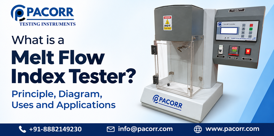
A melt flow index tester measures how much molten thermoplastic passes through a specified die under a defined temperature and load. It reports melt mass-flow rate, usually in g/10 min, or melt volume-flow rate in cm³/10 min when the instrument supports displacement measurement. Manufacturers use the result to compare material consistency.
Two bags of polymer granules can look alike yet produce different results on the same production line. A melt flow test gives the quality team a controlled way to investigate that difference before changing processing settings or releasing a batch. Its value comes from a repeatable measurement, a suitable material specification and an informed interpretation.
This guide explains the instrument, its working principle, calculations, test methods and industrial uses. It also shows how to select a tester and recognise results that need further investigation.
What is a melt flow index tester?
A melt flow index tester, also called an MFI tester, melt flow rate tester or extrusion plastometer, is a laboratory instrument for evaluating the flow of molten thermoplastics. Its core assembly is a temperature-controlled barrel, a piston, a specified test load and a precision die.
The instrument measures flow under a particular laboratory condition. It does not identify an unknown polymer or establish every property of a finished plastic product. For purchasing, the first question is therefore practical: does the laboratory need a mass-flow result, a volume-flow result, or both?
What is the working principle of a melt flow index tester?
The tester heats a prepared polymer sample in its barrel. After the prescribed preheating stage, the loaded piston drives the melt through the die. The laboratory measures either the mass discharged during a timed interval or the volume displaced as the piston travels.
Temperature, load, die geometry and measurement timing define the test. Changing one can change the reported value even when the material remains the same. A result without its test conditions is consequently incomplete.
The familiar ten-minute unit is a reporting basis. A valid measurement can use a shorter interval and scale the result to ten minutes according to the method. Simply allowing plastic to run for ten minutes is not a substitute for following the specified procedure.
Melt flow index tester diagram with explanation
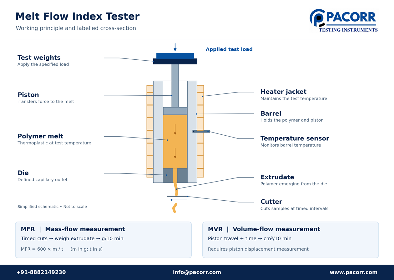
The heater surrounds the barrel, while a temperature sensor and controller regulate the test condition. The piston transfers the load to the polymer. Melt leaves through the die at the bottom. An automatic cutter can assist mass collection; a displacement sensor provides the information needed for MVR. A digital display alone does not establish that both methods are available.
Main components and their functions
| Component | Function | What the laboratory should check |
|---|---|---|
| Heated barrel | Holds the sample at the test temperature | Cleanliness, condition and temperature performance |
| Piston and load assembly | Applies the specified loading condition | Correct total load, free movement and alignment |
| Precision die | Defines the outlet geometry | Correct die, clean bore and dimensions within tolerance |
| Temperature sensor and controller | Measures and controls heating | Calibration at relevant temperatures; display resolution is not accuracy |
| Timer, cutter and balance | Measure extrudate mass over time | Matched collection intervals and suitable balance performance |
| Displacement sensor | Measures piston travel for volume-based testing | Supported measurement range and displacement verification |
| Software or recorder | Stores conditions, calculations and results | Units, material identity and traceable records |
For a conventional standard die, commonly cited nominal dimensions are 2.095 mm bore diameter and 8 mm length. Special procedures can use different geometry, including a half-die. The applicable standard controls dimensions, tolerances and use; the word “standard” on a quotation is not enough.
What is the difference between MFI, MFR and MVR?
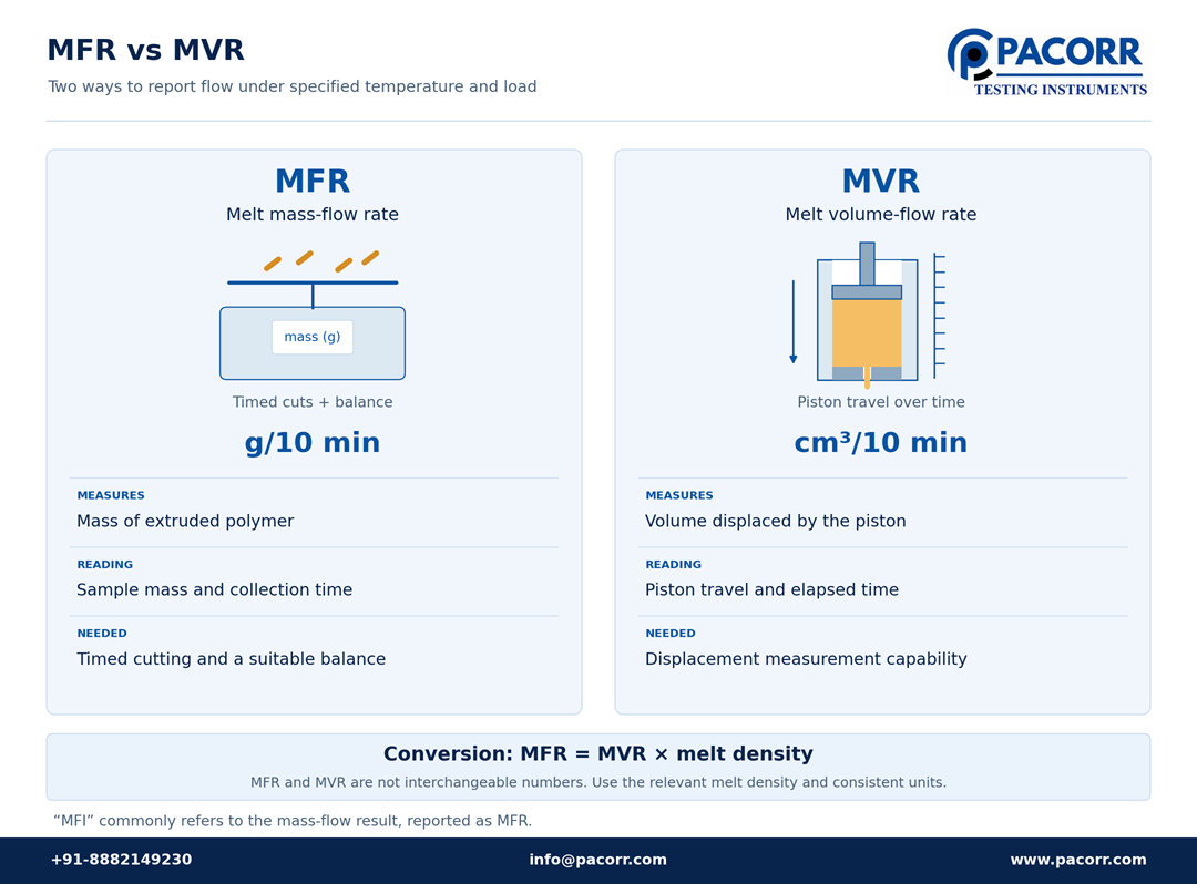
| Term | Meaning | Reporting unit | Practical distinction |
|---|---|---|---|
| MFI | Melt flow index | Commonly used for a mass-based result | Traditional industry terminology; specify the actual measured quantity |
| MFR | Melt mass-flow rate | g/10 min | Mass passing through the die per reporting interval |
| MVR | Melt volume-flow rate | cm³/10 min | Volume passing through the die per reporting interval |
| FRR | Flow rate ratio | Dimensionless | Ratio of flow rates at stated test conditions |
MFR and MVR are connected by melt density, but they are not interchangeable numbers. The density must apply to the material in its molten state under the relevant conditions. Room-temperature density from a general datasheet is not a reliable substitute. Filled materials need particular care because formulation and density affect a mass-based comparison.
How is melt flow index calculated?
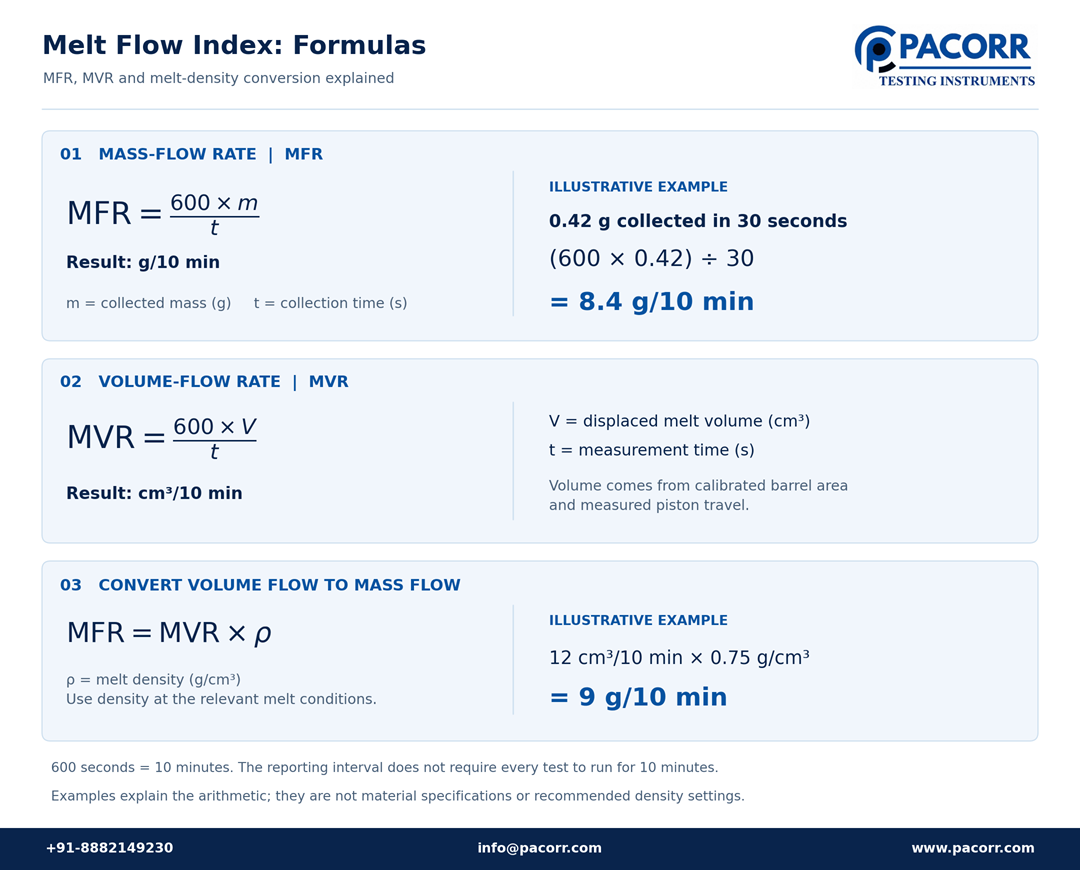
Mass-flow calculation
For collected extrudate mass m in grams and collection time t in seconds:
MFR = (600 × m) / t, expressed in g/10 min.
Illustrative example: a valid 30-second collection weighs 0.42 g.
MFR = (600 × 0.42) / 30 = 8.4 g/10 min.
If three accepted 30-second cuts weigh 0.42 g, 0.43 g and 0.41 g, their individual results are 8.4, 8.6 and 8.2 g/10 min. The arithmetic mean is 8.4 g/10 min. Apply the method’s validity and reporting rules before accepting that mean. Several cuts from one charge are not the same as independent repeat tests.
Volume-flow calculation
For measured displacement volume V in cm³ over t seconds:
MVR = (600 × V) / t, expressed in cm³/10 min.
The instrument obtains displacement volume from its calibrated barrel cross-sectional area and piston travel, using consistent units. Where an appropriate melt density ρ in g/cm³ is available:
MFR = MVR × ρ.
For example, an illustrative MVR of 12 cm³/10 min and melt density of 0.75 g/cm³ give an MFR of 9 g/10 min. These numbers demonstrate the calculation; they are not a material specification or a recommended density setting.
Which standards apply to melt flow testing?
The principal references are ASTM D1238, ISO 1133-1 and ISO 1133-2. Use the edition and procedure required by the customer or material specification. ASTM and ISO address the same measurement area but differ technically; a report should identify which was followed.
| Reference or procedure | Main purpose | Selection point |
|---|---|---|
| ASTM D1238 Procedure A | Mass-based determination | Timed extrudate collection and weighing |
| ASTM D1238 Procedure B | Displacement-based determination | MVR, with MFR conversion using appropriate melt density |
| ASTM D1238 Procedure C | Certain high-flow polyolefin measurements | Requires the specified half-die and compatible procedure |
| ASTM D1238 Procedure D | Multiple-load measurements | Supports flow rate ratio determination from a charge |
| ISO 1133-1 | Standard MFR and MVR methods | Procedure A is mass-based; Procedure B is displacement-based |
| ISO 1133-2 | Materials sensitive to moisture or time-temperature history | Tighter control of relevant temperature and timing conditions |
The ASTM procedure descriptions above are an orientation, not operating instructions. In particular, Procedure C does not mean every machine advertised as “A/B/C” can perform every specialised polymer test. Confirm the required accessories and current procedure.
Which plastics can be tested?
Melt flow testing is used for suitable thermoplastics, including polyethylene, polypropylene, polystyrene, ABS and various engineering polymers. The grade, formulation and method determine the preparation and test conditions. A material-family name alone is insufficient.
For example, commercial polypropylene datasheets commonly state results at 230°C/2.16 kg. That is a documented reporting condition, not a universal setting for all plastics or all polypropylene specifications. Read the selected grade’s datasheet and governing test method together.
PET, PBT and polyamide require attention to moisture and thermal exposure. Drying, protected handling and a controlled sequence may be necessary to avoid measuring changes created during the test. ISO 1133-2 addresses materials with relevant sensitivity.
PVC compounds also need deliberate method selection; ASTM identifies D3364 as an alternative method for PVC compounds. Do not assume an ordinary polyolefin procedure applies unchanged. Cured thermosets do not behave like remeltable thermoplastics and are outside the normal purpose of an MFI test.
How is a melt flow index test performed?
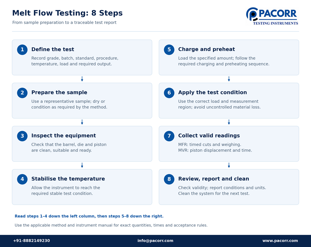
Use the following sequence to understand the workflow. Exact quantities, times, piston positions and acceptance rules come from the applicable method and instrument manual.
- Define the test. Record the resin grade, batch, standard, procedure, temperature, load and required output.
- Prepare a representative sample. Follow the required drying or conditioning instructions and prevent reabsorption of moisture where relevant.
- Inspect the equipment. Confirm that the barrel, die and piston are clean, suitable and ready for use.
- Establish temperature. Allow the instrument to reach the required stable condition before charging.
- Charge and preheat. Introduce the specified amount of material and follow the required loading and preheating sequence.
- Apply the measurement condition. Use the correct load and piston measurement region. Avoid uncontrolled material loss before measurement.
- Collect valid readings. For MFR, collect timed cuts and weigh them. For MVR, measure the specified piston displacement and elapsed time.
- Review and report. Check validity, repeatability and unusual observations; retain the conditions with the result. Clean the system for the next test.
Hot metal, molten polymer and heavy weights require suitable protective equipment and safe handling. Provide ventilation appropriate to the polymer and its safety information. Follow the equipment’s instructions for loading, cleaning and releasing components.
How should MFI results be interpreted?
A higher mass-flow result means that more material passed through the die under the stated conditions. Within a comparable material family, this often indicates easier melt flow. It does not automatically indicate better quality or guarantee successful mould filling.
Illustrative incoming-inspection decision: suppose a qualified resin specification accepts 7–10 g/10 min under a defined method. A measured result of 8.4 falls within that numerical interval. A result of 12.1 needs investigation. The limits in this example are invented to demonstrate a decision; they are not general limits for PP, PE or any other polymer.
Before rejecting the second batch, check the grade identity, preparation, temperature, load, die and instrument controls. If the result is confirmed, hold or release the lot according to the agreed quality procedure. Do not average an invalid test into a passing value.
MFR is influenced by molecular structure, but it is not a direct molecular-weight measurement. Materials with similar MFR can differ in branching, molecular-weight distribution, additives and behaviour at processing shear rates. Establish any correlation with product performance using separate evidence.
Uses and applications of a melt flow index tester
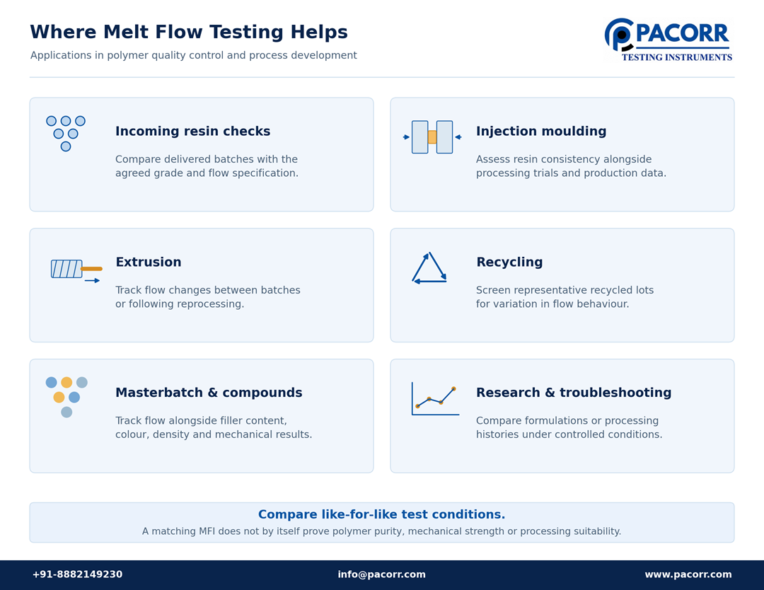
Incoming resin and supplier checks
An incoming-inspection programme can compare a delivered batch with its declared grade and agreed flow specification. Retaining supplier, lot and preparation information makes a disagreement easier to investigate. The useful question is whether the material matches the qualified requirement, rather than whether its MFI is simply high or low.
Injection moulding and extrusion
Moulders use flow data as one input when assessing resin consistency. Extruders can use it to track changes between batches or after reprocessing. A useful investigation compares laboratory results with recorded production behaviour: did the material change, the machine settings change, or both? Melt flow data should support that investigation without replacing a processing trial.
Recycling and reprocessing
Recycled feedstock can vary with its source, sorting and processing history. A sensible control plan tests representative portions and retains the identity of each lot. A single scoop from a mixed bulk lot may miss important variation.
MFR can help screen consistency, but a matching value does not establish polymer purity, odour acceptability, mechanical performance or suitability for a regulated end use. Pair the measurement with the other checks required by the intended product. Pacorr’s article on measuring melt flow index in recycled plastics provides related application context.
Masterbatch and compound development
Compounders can track flow alongside filler loading, colour, density and mechanical results. When formulations have different filler contents, consider whether MVR provides the more useful flow comparison. A density change can influence mass-flow values without representing an equivalent change in volume flow.
Research and production troubleshooting
Controlled comparisons can examine the effects of a formulation change or repeated processing. Keep the test conditions fixed and document what changed between samples. Pacorr’s discussion of melt flow testing for polymer quality control covers related manufacturing applications.
What affects accuracy and repeatability?
Temperature control, clean measurement surfaces and consistent sample handling are central to reliable results. A precise display cannot compensate for an unsuitable test method.
| Observation | Possible causes to investigate | Useful first checks |
|---|---|---|
| Unexpectedly high flow | Wrong condition, different grade or material change | Verify identity, temperature, load and preparation |
| Unexpectedly low flow | Restricted die, piston friction or incomplete preparation | Inspect and clean components; review heating sequence |
| Bubbles or interrupted strand | Entrapped air, moisture or other volatile material | Review sample form, drying, charging and conditioning |
| Drift during one charge | Thermal exposure, changing material condition or invalid measurement region | Compare timing and piston position with the method |
| Poor agreement between operators | Differences in handling, timing or collection | Observe the complete workflow and standardise training |
| MFR and MVR conversion disagree | Unsuitable melt-density input or measurement problem | Check density source, units and both measurement routes |
Bubbles are not proof of a single cause. Sample form and preconditioning both affect how material melts and consolidates. Investigate the preparation and the shape of the extrudate before assigning the variation to the polymer itself.
A repeatability problem should also trigger a review of raw observations. Preserve individual cuts or displacement readings and any excluded values with their reasons. A polished software report is useful only when its underlying measurements are valid.
Calibration, verification and maintenance
A practical programme checks temperature performance, test loads, die and piston condition, timing, the balance and any displacement system used. Choose checks and intervals according to the method, manufacturer instructions, usage and laboratory quality system. There is no single calibration frequency suitable for every laboratory.
Remove residue after testing using approved tools. Deposits can alter flow and friction; abrasive cleaning can damage the same precision surfaces being protected. Inspect the components and keep maintenance records. A suitable reference material can help detect drift between formal calibrations, but it does not replace them.
Distinguish resolution, the smallest displayed increment, from accuracy and temperature uniformity. Ask what a quoted temperature specification actually covers and how it is verified. Pacorr discusses these purchasing questions in its computerized MFI tester temperature-control guide.
Advantages and limitations of melt flow testing
Melt flow testing gives laboratories a compact result that is convenient to record, compare and trend. It can support routine acceptance checks and help decide which material changes deserve further testing.
Its limitation is equally useful to understand: one flow result describes one prescribed measurement condition. A capillary rheometer can assess flow over a series of shear rates for more detailed processing analysis. These instruments answer related questions at different levels of detail.
| Required information | Appropriate testing direction |
|---|---|
| Routine consistency at a specified temperature and load | MFR or MVR testing |
| Flow response across shear rates | Suitable rheological testing |
| Tensile strength or elongation | Tensile testing using the relevant specimen and method |
| Impact behaviour | Appropriate impact testing |
| Composition, contamination or identity | Suitable chemical or physical analysis |
For a broader quality programme, explore Pacorr’s tensile testing machine and Izod/Charpy impact tester. Select each test for the property needed; an acceptable MFI result cannot stand in for those measurements.
How to select a melt flow index tester
Write a short application brief before comparing quotations. Include the polymers and filled grades, expected flow range, required standard and procedure, temperatures, loads and daily sample volume.
Then ask the supplier to demonstrate the workflow on representative material. Observe charging, preheating, collection, cleaning and reporting—not only the displayed final number. For frequent grade changes, cleaning access may influence usable throughput as much as automatic calculation.
Confirm whether the quoted system includes the balance, cutter, displacement encoder, special dies, additional loads, software, calibration and training needed for the intended work. Ask for a sample report that shows the method and conditions. These are proposed purchasing checks; suitability must be established for the actual application.
Pacorr models to compare
The following options are listed on Pacorr’s product pages. Confirm the offered configuration and included accessories in the quotation.
| Model | Published focus or features | Requirement to discuss |
|---|---|---|
| Digital MFI Tester — PCMFIT-1 | Digital control and routine thermoplastic flow testing | Mass-testing workflow, collection and reporting arrangements |
| Melt Flow Index Tester — PCAMFIC-1 | Automatic cutting and weighing, MFR calculation, Windows software and RS-232 connection | Automation scope and any separately required displacement capability |
| Method A/B/C MFI Tester — PCMVR | MFR/MVR measurement, encoder, touch-screen control, USB result storage and listed half-die capability | Required procedure, melt-density workflow and supplied dies and loads |
Do not assume that “computerized” means the machine measures MVR, or that an automatic cutter makes the complete test automatic. Specify the measurement function required and confirm it in the offered model.
What determines the price?
The price depends on measurement capability, automation, accessories, software and service scope. Compare complete configurations rather than headline amounts. A useful quotation should identify installation, training, calibration, taxes, delivery and recurring consumables where applicable. Request a current model-specific price from Pacorr.
Frequently asked questions
Does a higher MFI mean stronger plastic?
No. MFI describes flow under specified conditions. Strength must be measured using the relevant mechanical test. Any relationship between flow and strength must be established for the material and application rather than assumed from the MFI value alone.
Must the test run for exactly ten minutes?
No. The result is expressed on a ten-minute basis. The actual measurement interval follows the method and material flow rate, and the measured quantity is normalised accordingly.
Can two values obtained at different loads be compared?
They can be studied as different test conditions, but should not be treated as equivalent acceptance values. A deliberately defined flow rate ratio can describe the relationship; report both conditions and the ratio convention.
Can an MFI tester measure viscosity directly?
A standard MFR result is not a viscosity value in Pa·s. Melt flow reflects rheological behaviour under the test conditions, while detailed viscosity characterisation requires an appropriate method and instrument.
Can recycled and virgin polymers have the same MFI?
Yes. Similar flow values do not establish identical composition or performance. Use the required identity, contamination, mechanical and end-use checks before deciding that materials are interchangeable.
What should an MFI test report contain?
Identify the material and lot, instrument, standard and procedure, sample preparation, temperature, load, die, measurement intervals, result and units. Include relevant observations, repeat measurements and validity decisions. For converted MFR, retain the melt-density value and its source.
What is a good MFI value for injection moulding?
There is no universal value. The suitable range depends on the resin grade, part design, processing conditions and required properties. Start with the qualified material specification and verify performance in the intended process.
Choosing a tester for a useful quality decision
A melt flow index tester is most valuable when the result leads to a clear action: accept a qualified material, investigate a change or request additional testing. That requires a suitable procedure, controlled preparation and records that make the result comparable.
To discuss a Pacorr configuration, share your resin grades, expected flow range, required MFR or MVR output, standard, temperatures, loads and daily workload through the Melt Flow Index Tester product page. Ask for a demonstration and quotation against those requirements.